


Get any of my plans now for only $10 !!! This sale is only for 30 days.

Get any of my plans now for only $10 !!! This sale is only for 30 days.
So today marked the second day of the project and before I could get started on a side project and that was a Pipe Clamp glue-up jig and I created its own blog entry and you can find it in the link below.
Started to clean up the dried flight blanks that I did yesterday
One more glue-up
I wont go into too much detail on this as I created a project blog detailing the build, but I will say this. After yesterday’s glue-up I was very frustrated both during and after . Glue-ups need a good system and a little rehearsal because my system was flawed it didn’t matter how much planning went into it, it would never be a pleasant experience.
I had researched making this some time ago but it was always put on the long finger and put onto my to-do list, which I never got to do. But because this project had a lot of different parts in gluing it up I tried a method that didn’t work and decided before I move one more step in the current project I needed to get this done.
Anyway the project is super easy and if you have scrap plywood lying around it will not cost anything to make. Its basically a jig that has a front & back with 2 two sides. It can be broken down and stored away when not in use.
Below is the finished image of the jig, but [please feel free to go over to the blog entry for more details, the link is below)

Here is the finished clamping jig
The boards needed a good bit of clean-up , and the blanks developed a bow in the middle so I tried to address this by turning the 5’ sections on there sides and trying to level it by running it through the table-saw blade, I really dont recommend doing this as it unsafe. But since I don’t have a planer or joiner I had to try something. It came out OK but tomorrow I will need to use my belt sander with some course paper to true the face up a little more.
Below you can see how I left it today

Here is the blanks as I left them today, I have some wood burn to clean up and then start turning these in beer flights, the fun stuff.
The last thing that I wanted to get done today was to glue-up that final blank that I could luckily make after realizing that I had enough scrap pieces left from yesterday, I came up with a flight that is a little narrower but had maple & sapele woods that I could turn in another 2-3 flights.
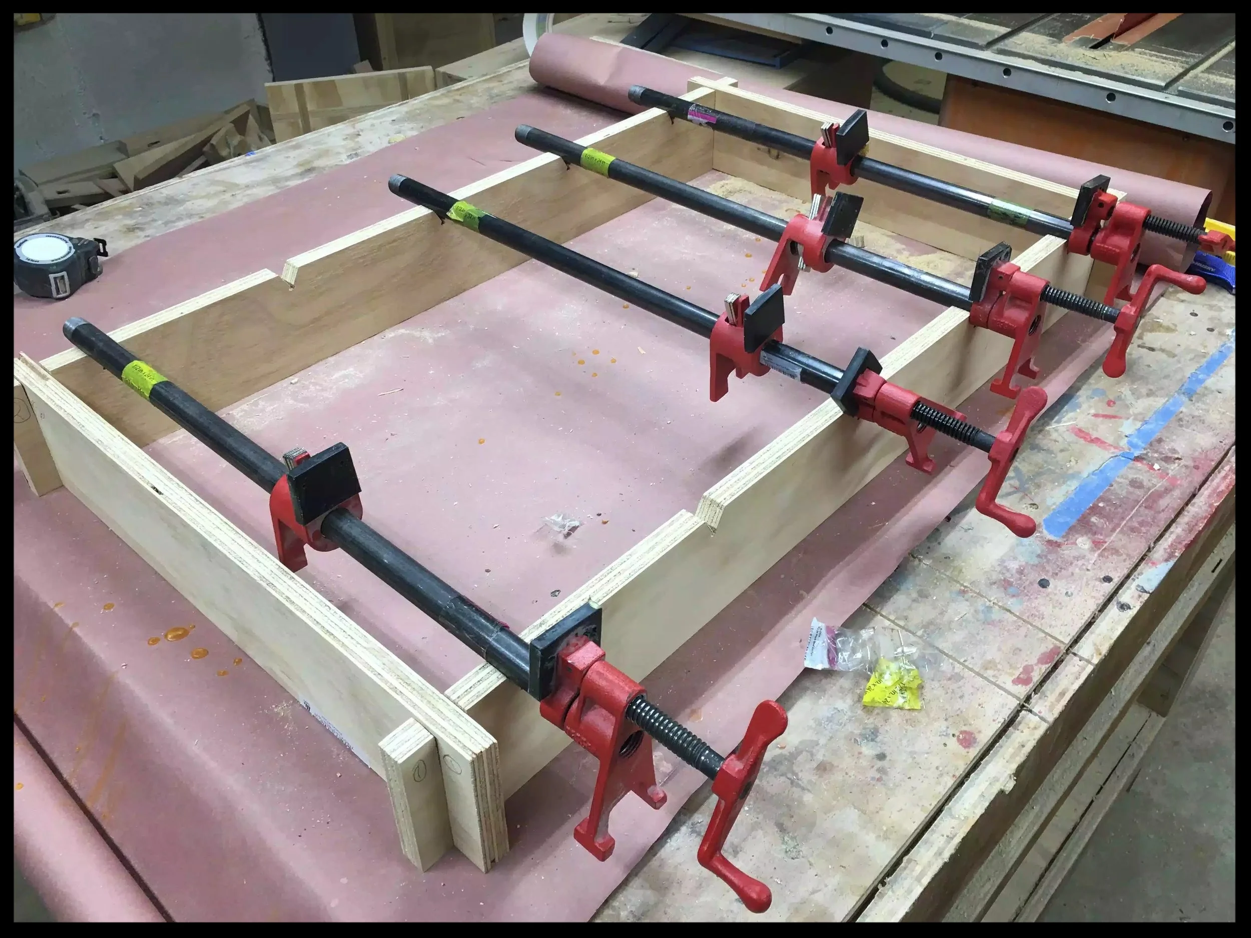
Another bonus was that I could get to use the new glue-up jig that I just made and man o man was it a much better experience and hopefully will result in a much flatter glue-up than yesterday’s.
You can see some pictures below.

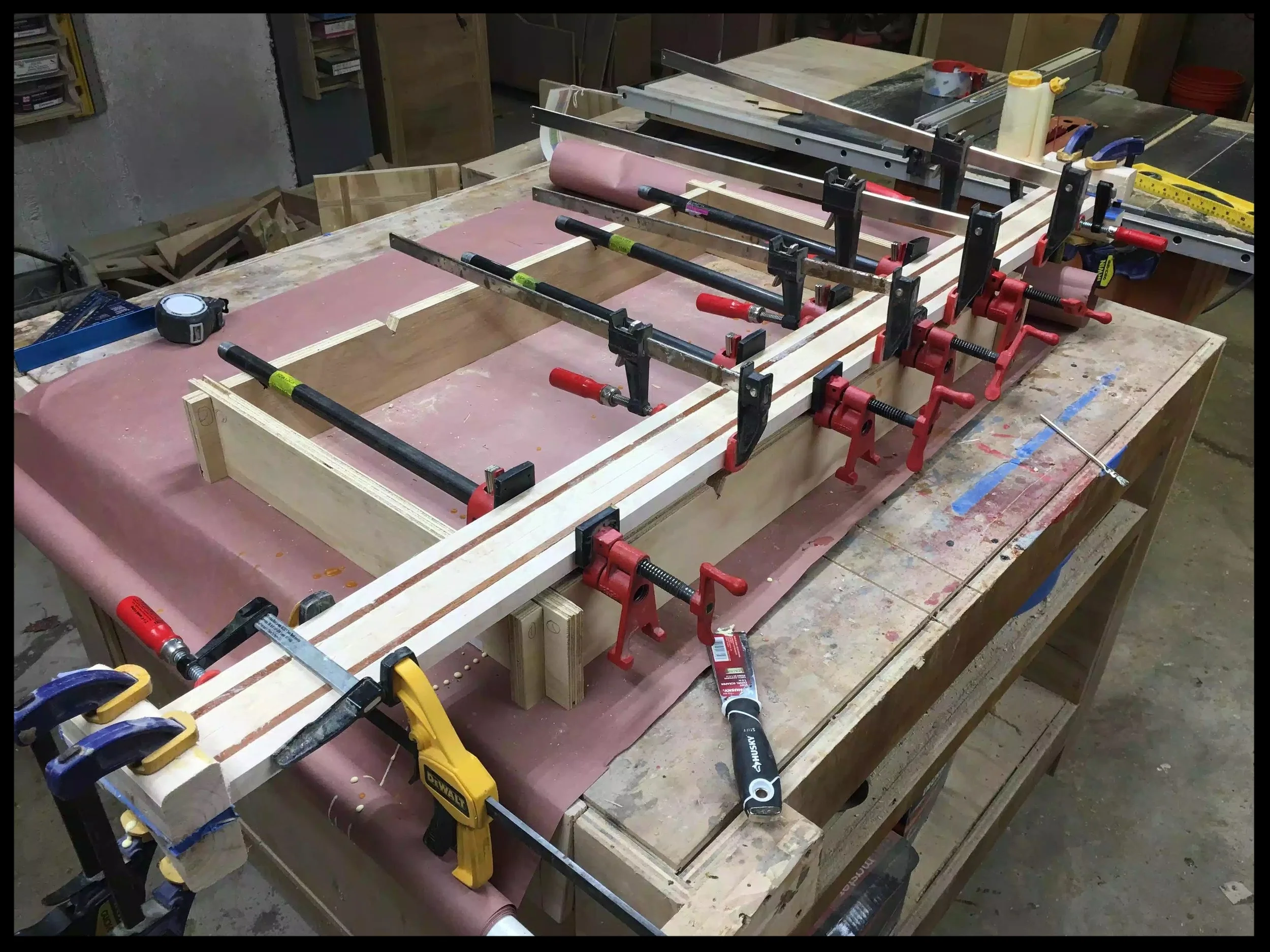
Here you can see the different design in the clamping jig. Most of the blank is maple with 2 contrasting Sapele pieces on each side.

The jig worked an absolute charm

Another picture of the jig in action.
Well that is what I got done today, thanks for tuning in and I’ll catch you again later.
Clean up the blanks with some sanding and make sure they are true and flat
Hopefully I can start cutting the blanks up so as that I can move onto the next step, layout.
So after yesterday’s glue up fiasco I decided today that I would make a clamping station, something that I have been meaning to do for a while now and I will describe the project below.
Research
Materials
Design
The Build
I found 2 articles online that I used to design this jig, one I found on one of woodworking pages that I am a member of and the other was a YouTube video, links to both are below.
I really liked this concept because of a couple of reasons.
It was quick to make
I could use scrap plywood, so it didn’t cost anything
I could collapse the jig and store until I needed it
I could customize it, I could make any length I wanted depending on the usual size of glue-ups I do, I could also make different sized stretchers depending on what size clamps I would be using.
The other resource that I found was a YouTube video created on a channel called the Woodworkweb and you can see it below.
This guy took a different approach to how the pipe clamps would be secured into the jig, instead of using the half-circle approach , he thought that there was still too much movement when the pipe clamp was sitting on the jig so he created a “V” so as that the pipe would be more secure inside the jig.
He demonstrates this in the video below.
I decided to use scrap plywood that I had on hand and I couldn’t think of a better project because I could clear some of my stock.
I had a quarter sheet of plywood, so the dimensions I used was 4” high x 40” long piece for the front and back of the jig. I also made 2 different sized stretchers or sides of the jig so as that I could use different sized pipe clamps depending what I was actually gluing up, so I made the stretchers 24” & 36” wide.
I turned to my trusty Sketchup to design the 3D Version of the jig. You can see some pictures of the plans that I made below.

Here is the finished design.
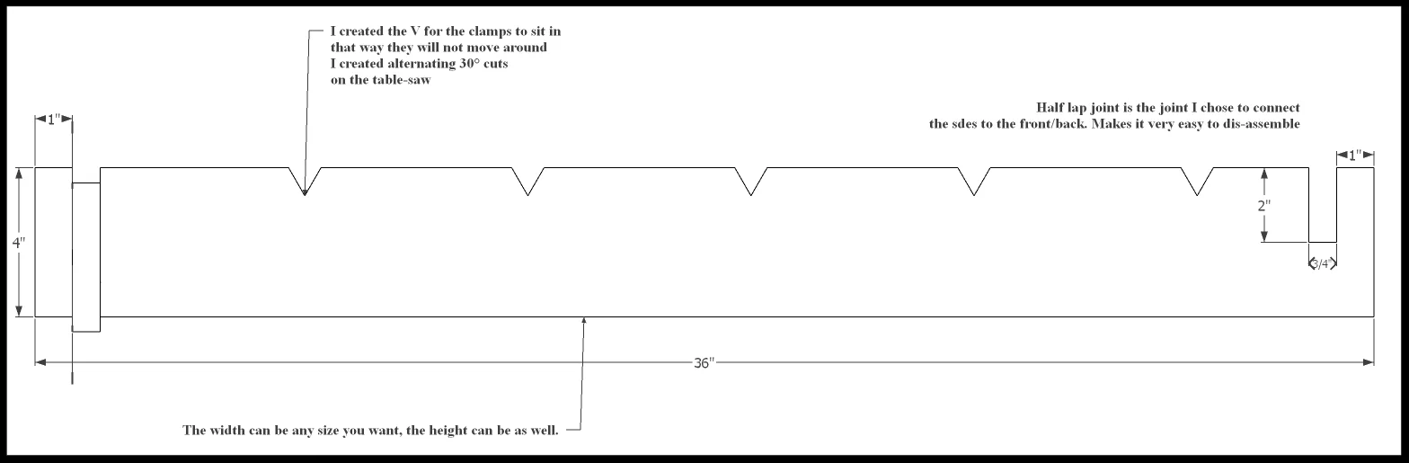
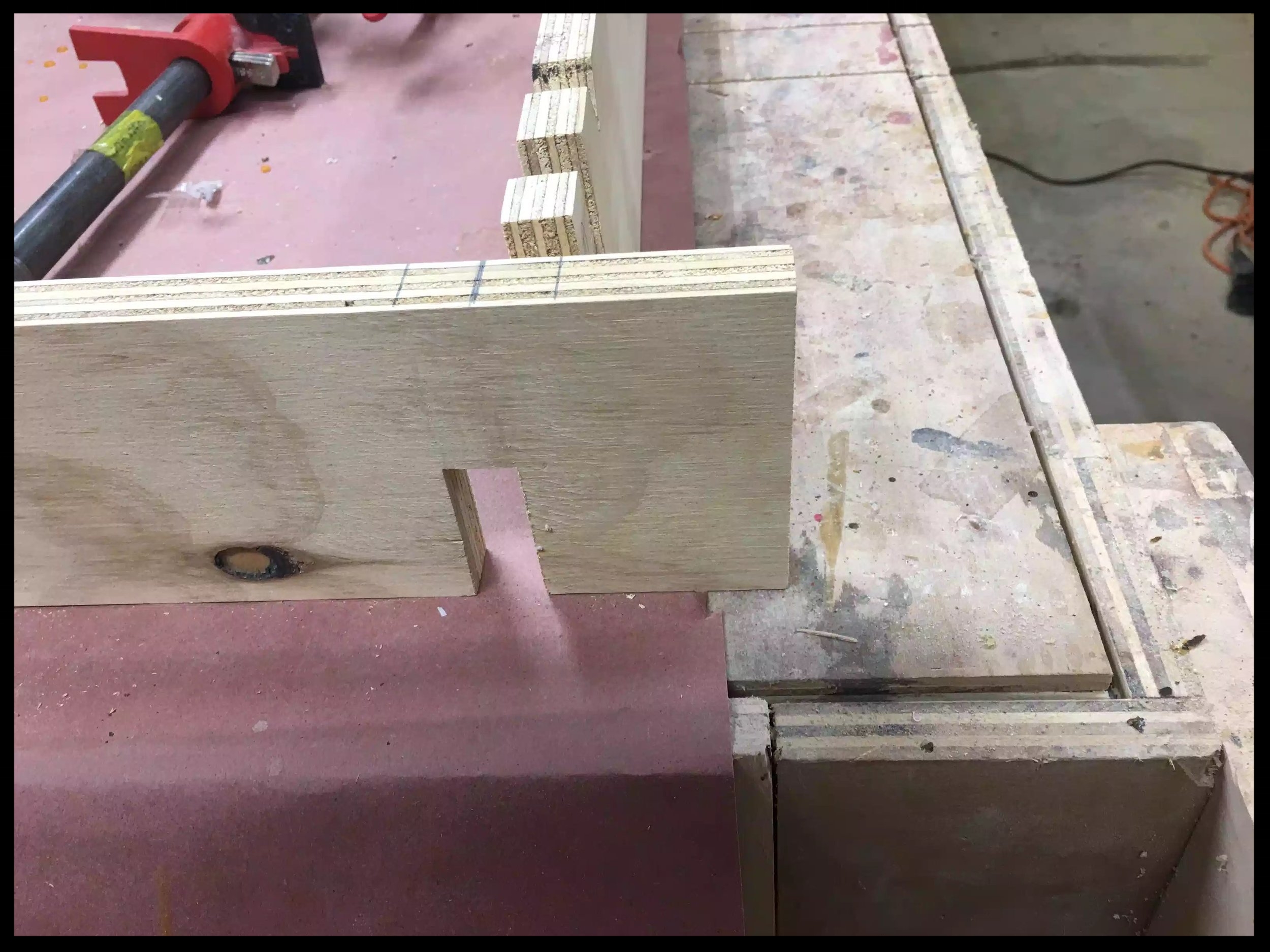
Here is the front & back clamp rail, the front & back are mirror images of each other, you can see the V cutouts that I made and the guy is absolutely correct the bar clamps do sit more securely in the jig.

Here is the side , again each side is the exact same as each other, and the only thing you need to do to them is create the half-lap joint that creates the joint to secure them to each other, it is also what enables the jig to disassembled and stored away. One thing to note is the sides has the bottom part of the joint cut and the front/back has half-lap cut into the top part.
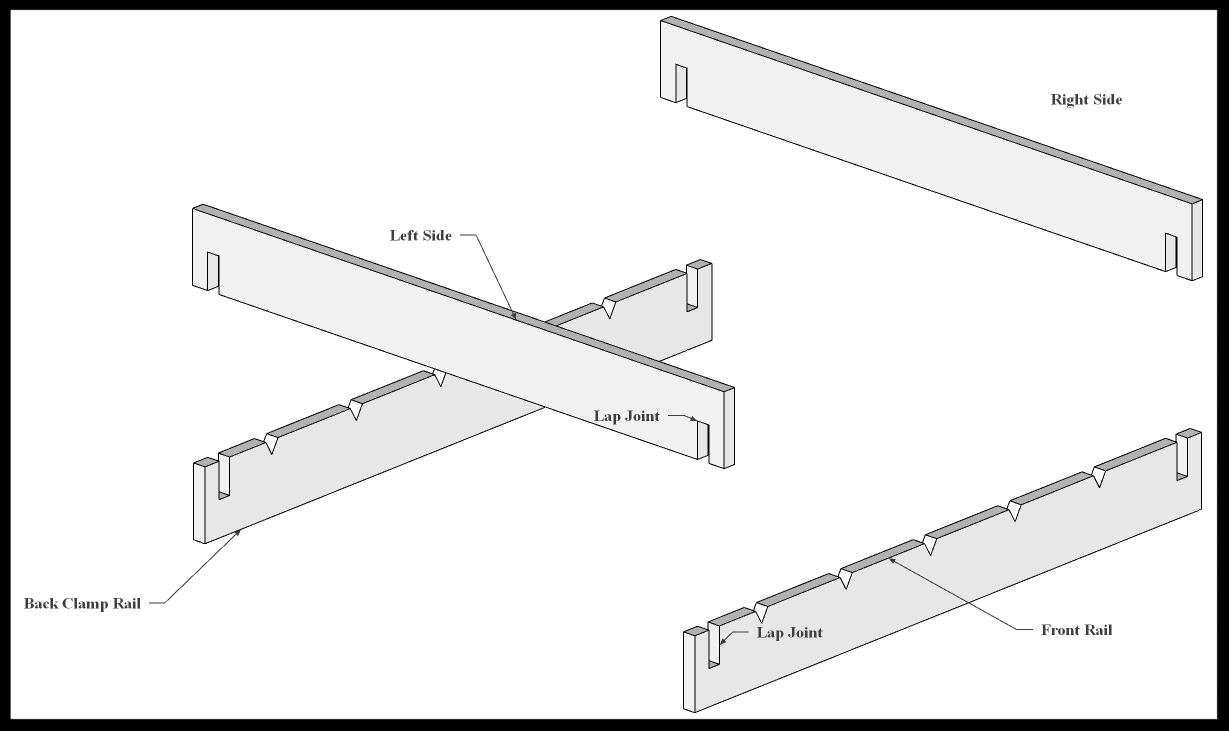
Here is an exploded view of the jig, you can kind of see how the parts fit into each other.
I included a link to the free plans at the bottom of the post.
STEP 1 : I cut the plywood to size which was the following
2 Pieces at 4” wide x 36” (front & back pieces)
2 Pieces at 4” wide x 36” (sides)
2 Pieces at 4” x 26” ( these will be used with 24’ pipe clamps)
STEP 2 : I marked out where the half-lap joinery needed to be placed so I measured 1” from each side of the front/back parts then using a piece of scrap of plywood marked the position of the lap joint. To avoid making any mistakes mark out the waste for the lap joint ,on the front & back the lap should be removed from the top. The side pieces should have the material removed from the bottom. I could of used my dado stack in the table saw to remove the half-lap waste but 4 only 4 cuts I decided to just leave the regular blade in the saw and clean up with a chisel.
STEP 3 : I needed to add the “V” notches to hold the bar clamps in place.
To do this I tilted the saw blade to 30° and lowered the blade to about 3/4” high and made a pencil mark on my miter fence to determine where the starting point of the blade entering the work-piece and then made another adjacent mark about 7/8” away from the other, this marked bot sides of the cut, thus creating the V. I spaced out each V about 5-1/2” away from each other and I got this measurement by laying out 2 bar clamps next to each other to determine what space I needed so as that hat the clamp handles could rotate freely to tighten the clamp without bumping into each other.
Basically that is all you need to do, I posted pictures below to show some of the features of it and I actually got to use it today for another Project that I am working on “The Craft Beer Flight Project”
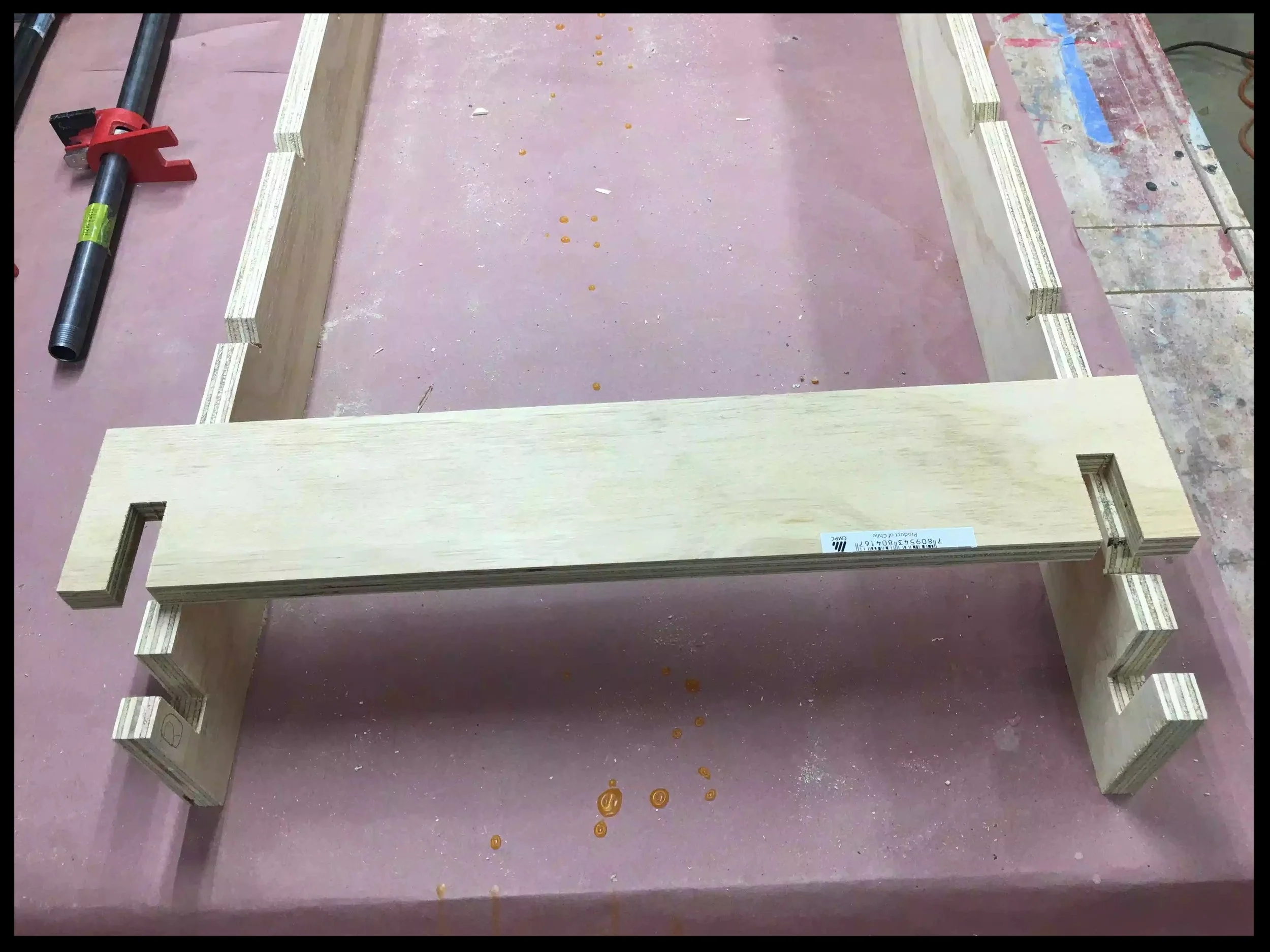
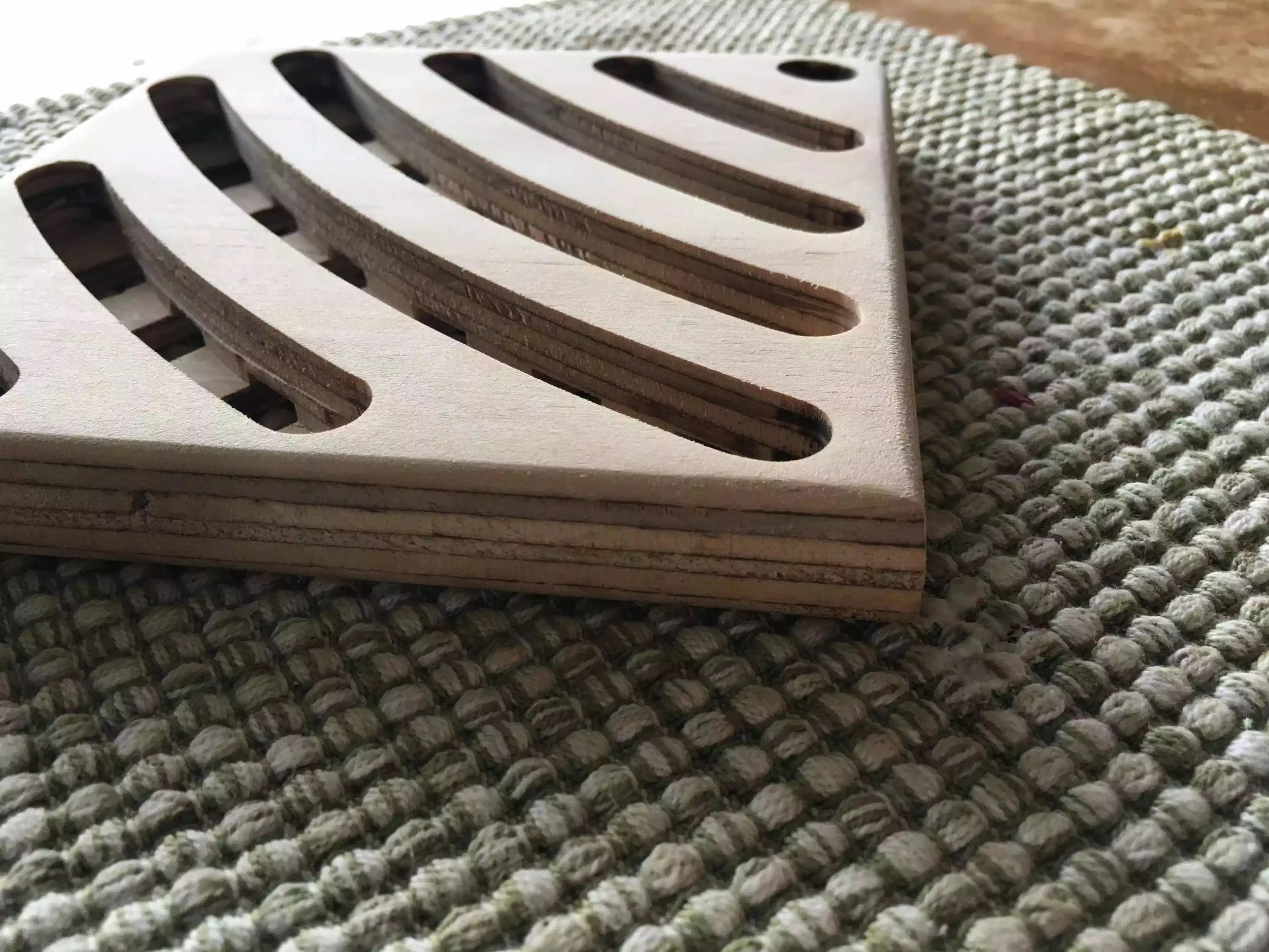
Here is the finished jig.

Here is a close-up of the half-lap on the front part of the jig, you can also see the V notched in
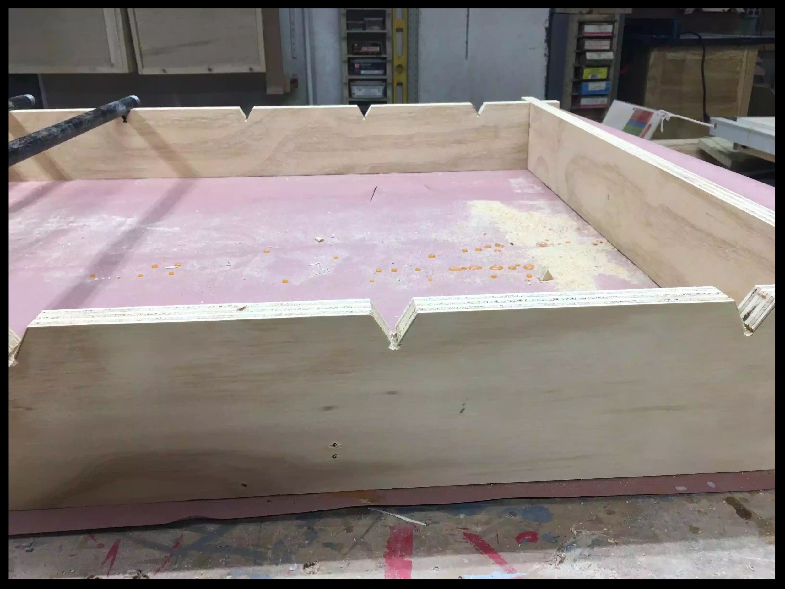
Here you can see how the clamp sits in the V notch and it works awesome
Here is one of the sides with the material cleared on the bottom of the joint.
Here you can the side piece with the completed half-lap material removed.
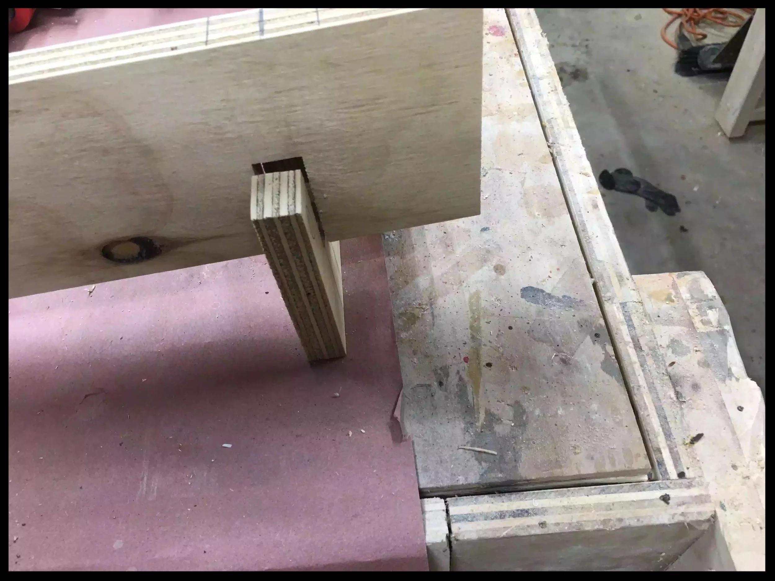
Here is how the half-lap works its an extremely strong joint.
Finally the jig in action, I should have made this a long time ago.
So now that I have solved my glue-up problem I can move back to my main project. I hope you enjoyed this little project, its not the fanciest project but it sure is a functional one.
So today I started making the craft beer flights and boy was it a messy start, mainly because I needed to do pretty big glue-ups. They were not widest glue-ups but they sure were plenty long, anyway more about that later.
Ripping all the wood on the table-saw
My Designs
Glue-up Prep
Glue-Up
So I needed to take all the wood and cut them to the dimensions that I made on my plan, I ultimately wanted a 4-1/2” wide flight and using 3 species of wood which were Sapele, Maple and Walnut. So I needed to take these boards and cut them into smaller strips.
so I installed a rip blade in my table-saw and also placed a feather-board in place so as that the wood piece would move while I was ripping it.

Here is the table-saw set up I made with the feather-board in place
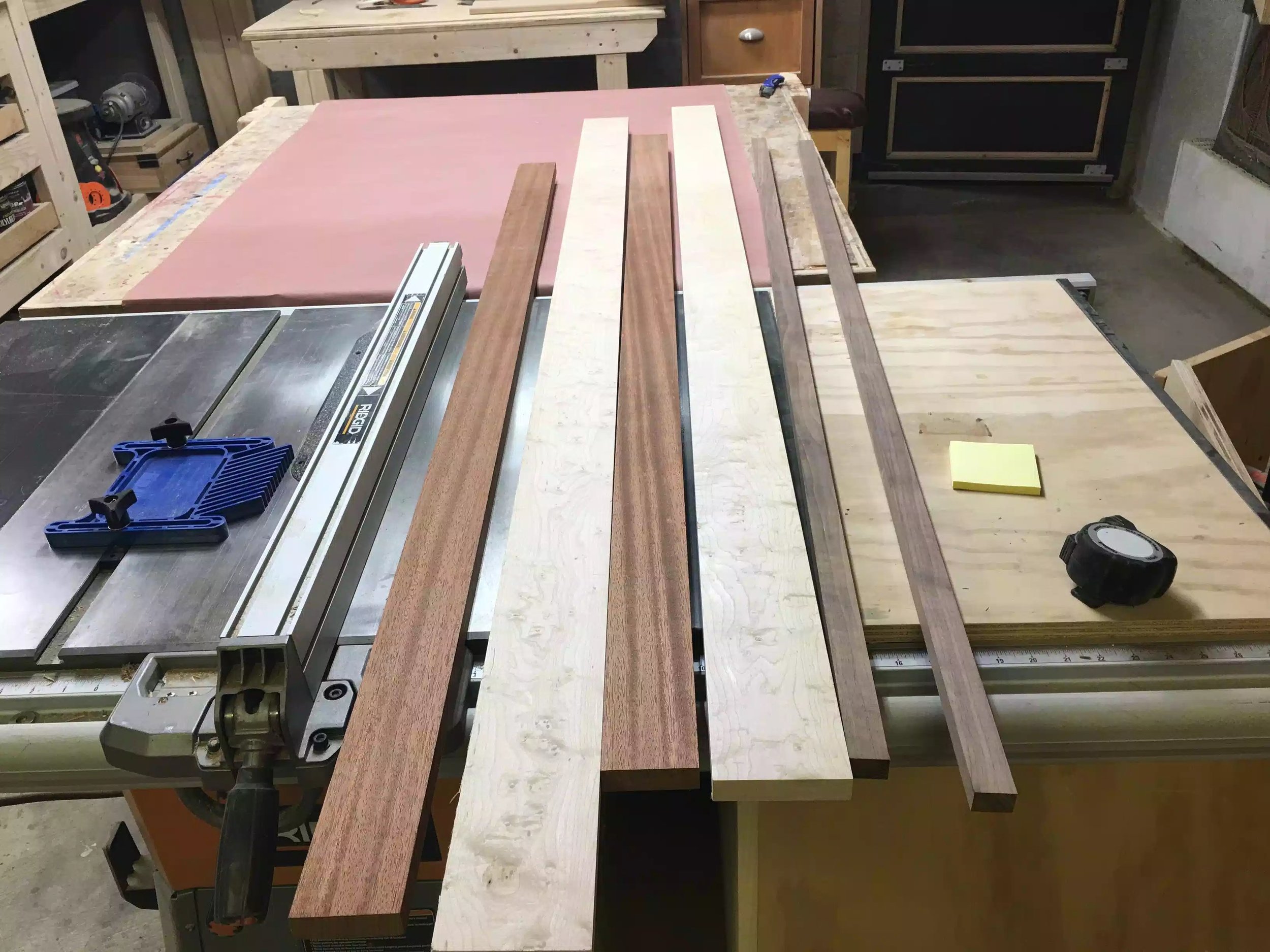
Here is the 3 species of wood that I will be ripping.

Here are all the pieces ripped and came out great as there was no burn marks on the wood as I used a rip blade.

Here is another close up of the boards that were just ripped.

So here is the design I came up with I really like the contrasting woods and should come out great, I was lucky enough to make another design by some of the leftover off cuts that I had.

Since I had more maple and sapele left over I could make this design as well its really nice as well. So what started out as making 6 flights I will be able to make 8-9.
The glue-up was going to be a little complicated because I wanted to glue up three 5 foot sections all at one time. I wanted a system where I would clamp all three together with dividers between each of the glue-ups and that way I would not need a ton of clamps, but that turned out to be not the most efficient way and I didn’t get one of the glue-ups done. I was using Titebond II and the open time was not long enough to fit in 3 glue-ups so I just did 2.
I really dislike the method I used and really need to rethink my process, I use 3 pieces of plumbing white pipe on top of wooden risers as you can see in the picture below, and the dividers that I used to separate each glue-up were different heights so I couldn’t use clamping cauls, I will know more tomorrow after the glue has set but I think I am going to have a fair bit of surface sanding because I don’t have a planer.
I also had to make a trip to the local big box store to purchase more clamps as the clamps I had were too short so I got the Bessey Pipe Clamps and a couple of 24” black pipe pieces. After I finished for the day I started researching better clamping set-ups If my shop was a little bigger I would just make a clamping table but since that is not possible I found another method which is portable and can be broken down and stored away when not in use. I think I am going to make this tomorrow and probably make a few different rail sizes depending on what size clamps I will be using at any specific time.

As you can see its a front and back rail with stretchers on either side, he notched out half circles to accommodate the pipe clamps, The stretchers are help together using a half-lap joint and when not in use can be just pulled up and the jig can be stored away.I think I will make mine the same but I will add different sized stretcher depending the size of clamps I will be using, they usually range from 12” - 36”. Click here for the website I found this on.

Here are the white PVC pipe that I have nesting in some scraps, but didn’t work great because the scraps kept falling over.

The idea of the white pipe was that it gave the work-piece a flat surface to sit on, and it also afforded me to add height to the glue up so as that I could place clamps on the bottom and top surfaces of the work-piece.

Here is the final pieces with all the glue applied, I will not be doing this again. But we live and learn.
I really do like the patterns on the flight and think they will be really nice when finished.
That’s all I got done today and thanks for reading.
Build the pipe clamp glue-up jig… I might need to get some plywood but I am not sure if I have enough scrap to get this done.
If I have enough time I need to do some surface sanding on the 2 glue-ups I got done today and I would like to get the other glue-up completed hopefully using the new jig.
Some times its beneficial to make a prototype of the project that you eventually want to make especially when you are marrying 2 elements together, most of the time on a project this size its not always necessary but I had to many unknown measurements especially considering putting glasses in the flight, and also it helps to have a tangible object in your hand to see any design elements that might look great on a computer but look bad on a finished project.
Below are the steps I took to make the prototype:
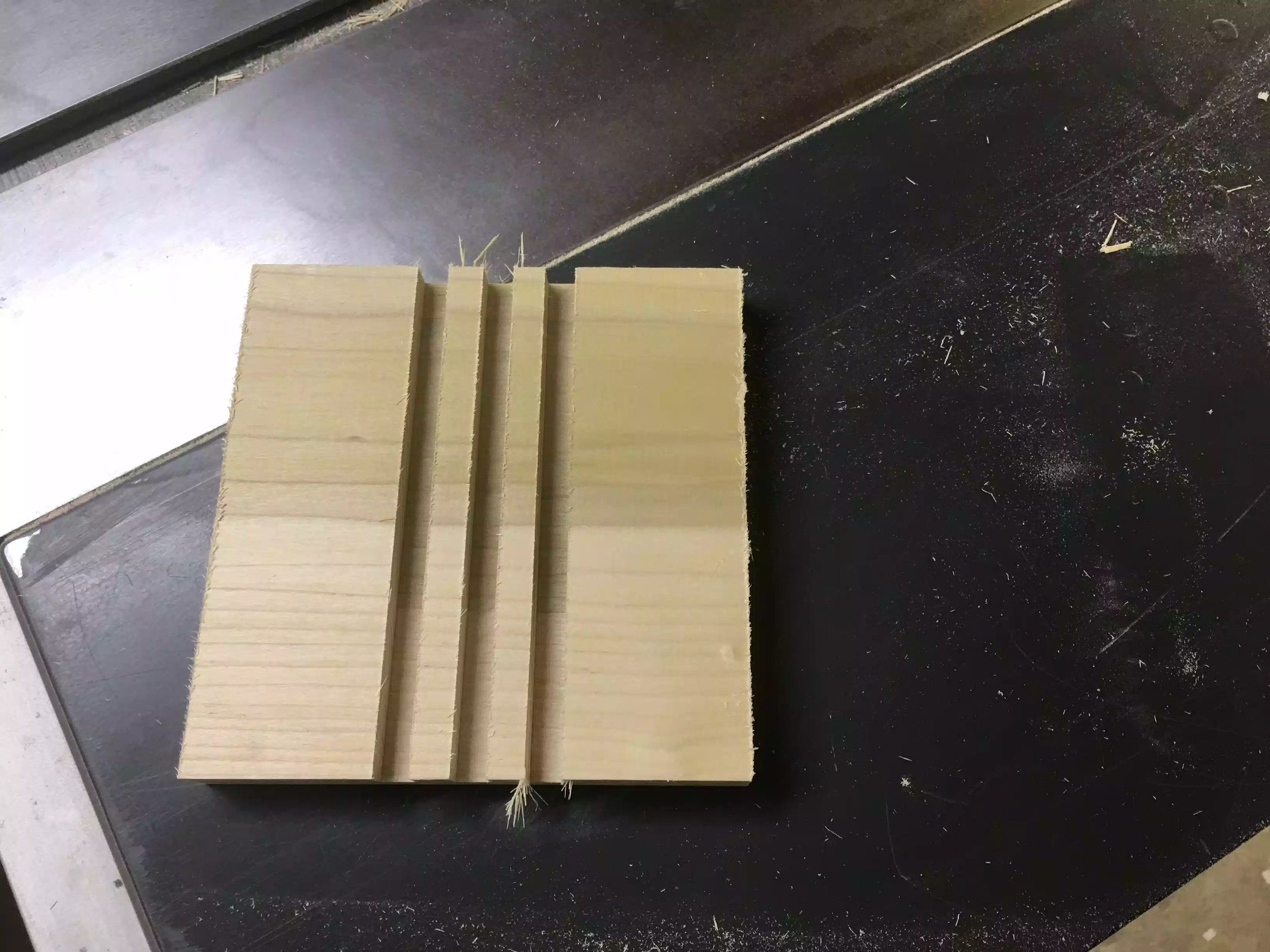
I used plywood to make the prototype as I had some on hand, but really any material could be used to make it. So my first step was to cut 3 pieces of plywood to my dimensions for the beer flight, a top and 2 sides
Next I had to do some layout
Cutting the circles & Circle cutting tools
Cutting the dadoes
Router Work
A little assembly
There are only 3 parts to the beer flight, the top and two sides. Below is a picture of the plywood parts, when I actually get to making the flight I will be using 3 species of wood that I will need to glue up but I don’t have to do that now and this prototype project only took me like 90 minutes to make.

Here are the parts, the back pieces are the sides and the front piece is the top of the flight.
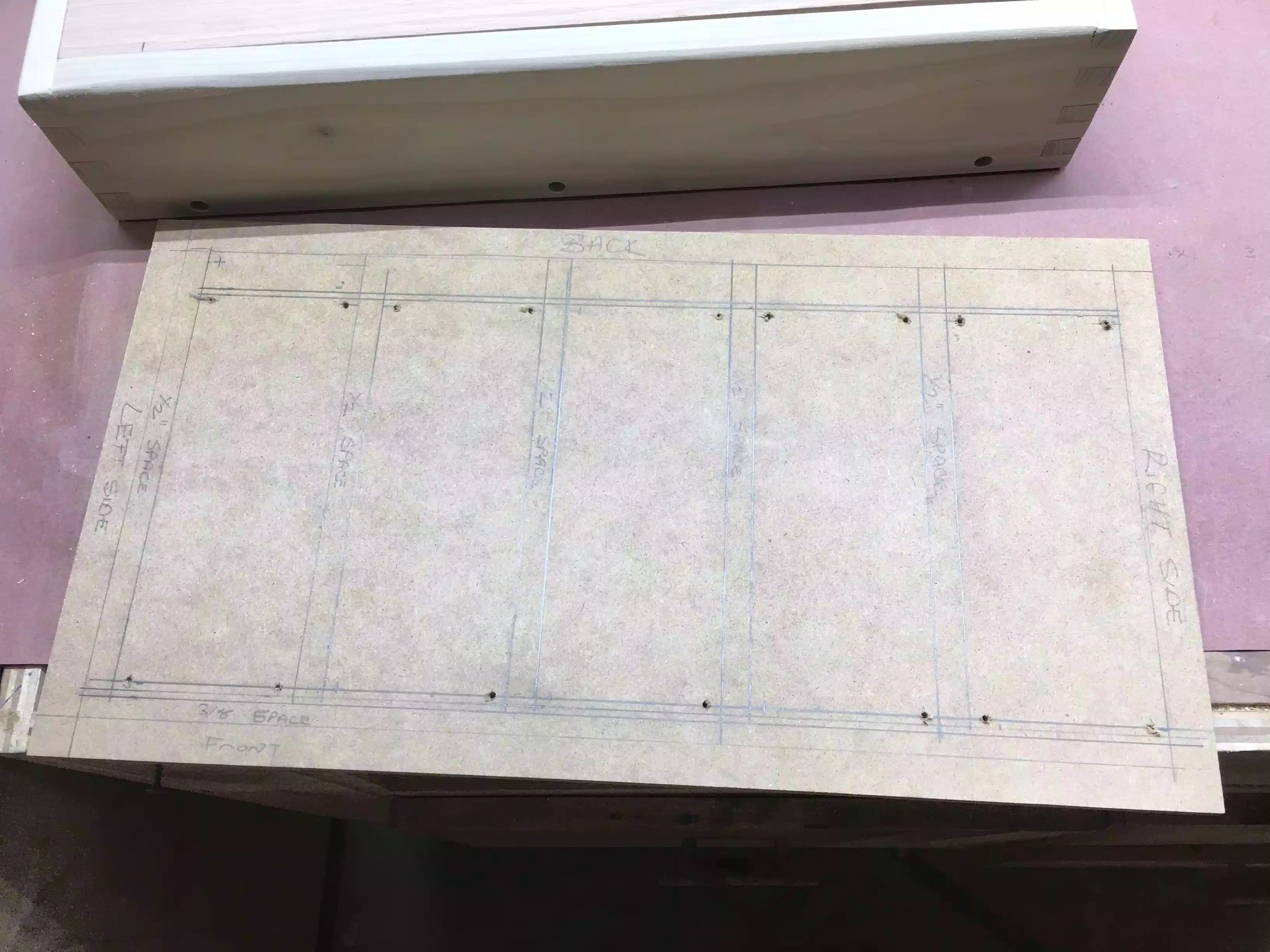
There was quite a lot of layout work in the design phase of this project, so I took all my dimensions from Sketchup and that was one of the main reasons I am making this prototype. Here are some of the dimensions that I needed to layout
Centering the holes for the glasses on the flight top, making sure to keep clear of the left & right legs that were underneath the top. So I measured 2-3/4” from each of the sides (left & right), the second measurement was 5-1/4” repeat that measurement as i did on the first. I also need to draw a centering line 2-1/4” from the top edge and where these lines intersected was the center hole I would use my hole saw to drill out the piece (more on that later)
Next for determining the center hole for each of the 4 holes that will be cut for the glasses. I needed a 2” diameter for each hole and I also wanted a 1/2” space between each of them holes. This was another reason for the prototype because I wanted to make sure that the 1/2” space was enough so as that the glasses didn’t bump into each other as the style of glass I was using had wider top than bottom.
Next piece of layout was for the feet mainly because I was cutting 3 half-circles into each piece. A half circle was to be cut halfway up the left & right side of each foot and that hole diameter was 1” and one half circle on the bottom and that diameter was 2-1/2” wide centered on the foot.

Here is the layout done on one of the feet.

Here is he layout on the top piece, I also drilled pilot holes for the hole saw to track correctly.

Here is the layout for the dadoes, I measured 1/2” from each side and drew lines indicating where I wanted the dado to go, that’s later.
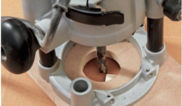
So since all of my layout lines are in place I needed to actually cut the circles that I incorporated into the design. I used three different diameter hole saws (1”, 2” & 2-1/2”)for this and I also used my bench-top drill press doing this, you could use a handheld drill but it would be difficult especially on the half-circles.

I used my Milwaukee Hole saw set as it had all the circle saw diameters that I needed, what a great tool even in a under-powered drill press like mine.

Here is a close-up of the 2” diameter hole saw.

Here is my current drill press set up, if you would like more information on how I made the drill press table or drawer cabinet you can find more information here.
Cutting the circles started with me cutting the 2” diameter holes in the top, I needed to cut 4 of these as they will house 4 glasses.

Here is the work-piece positioned under the hole saw, the work-piece was turned end for end to get both left and right sides done, the saw did a great job as I didn’t get any burn marks on the work piece.

Here is a close-up of the circle cut-out.
Next I needed to cut out all the half-circles in the feet and I needed a method that would not waste any of the wood I have, So I came up with a method on the drill press that allowed me to cut the feet to exact dimensions not bigger, sure I could of made an overside work-piece and drill the full circle out and cut the circle in half but that meant wasting wood.
So the method I came up with was to use 2 sacrificial plywood scraps to go either side of the the work-piece which were stuck in place with double sided tape on my drill press table and support the entire cutting edge of the hole saw and when I was finished I could put another work-piece in place and repeat until my sides were milled.
also another thing to note that the feet had 2 different diameter half-circles to be cut if you remember from my layout.
Below are some pictures of the process.

Here is one of the sides in place and to the left and right are 2 sacrificial pieces, he idea was to make sure that the entire cutting surface of the hole saw had something to drill into , thus keeping the hole saw tracking in the downward direction and not chewing up the main piece, and it worked out great. This picture shows me drill the 1” diameter holes on the sides of the feet.

Here is another shot showing all the holes drilled out.

Here is a close up of one of the sides. Came out great
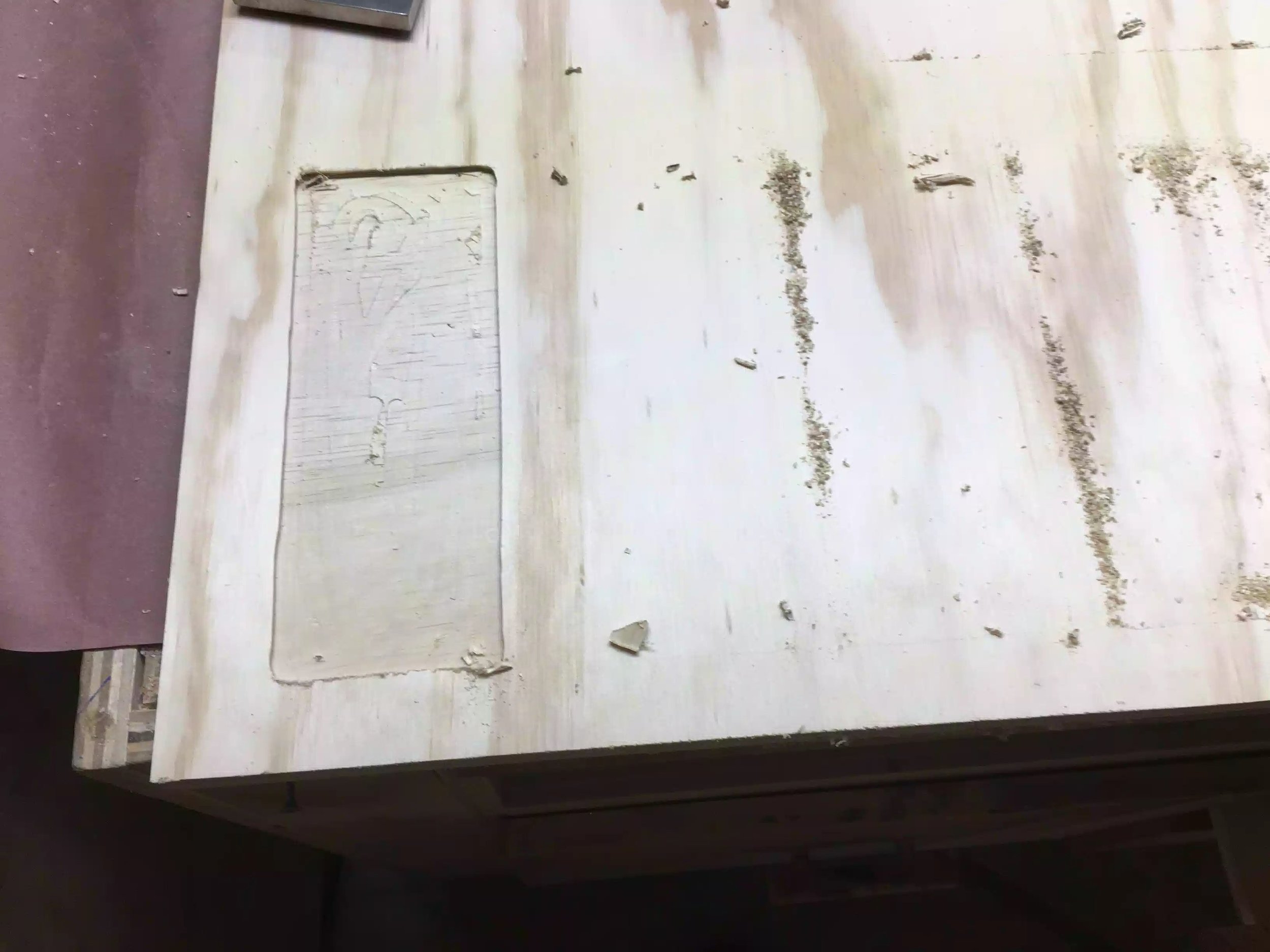
The joinery method I will be using to join the feet to the underside of the top will be dadoes. These are just grooves that I cut out at the table-saw with my dado stack, the width of the dado stack is determined by what thickness wood you are using. I measured 1/2” from the left and right side.
The other main reason I was doing a prototype was because I wanted to make sure that when the glasses were sitting in the flight that they didn’t interfere with the feet in any way, and thank god I didn’t.

Here is the bottom face of top and you can see the 3/4” wide dado that is also 1/4” deep into the top.
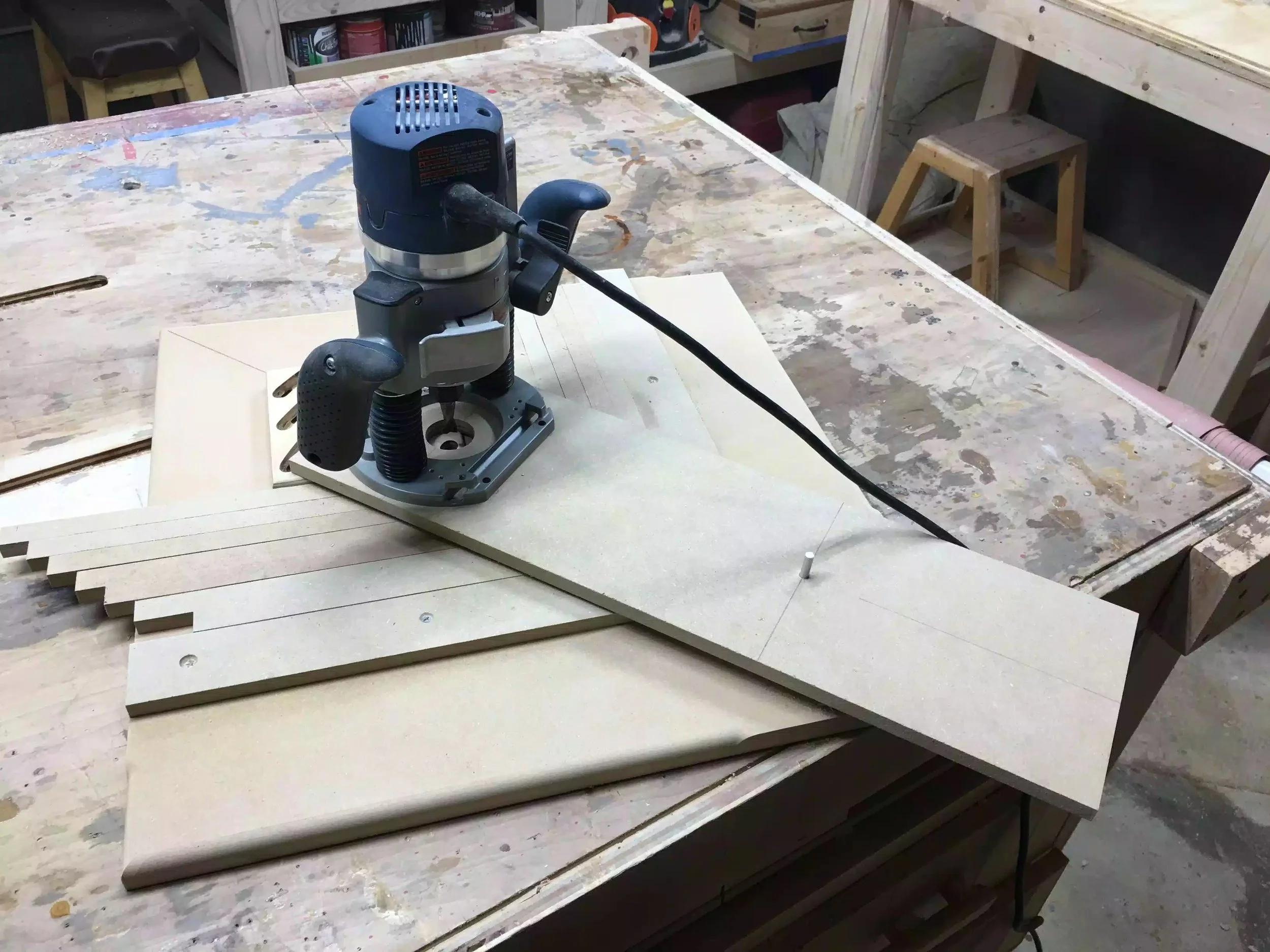
Finally I wanted to add some decorative elements to the flight so I used my router with a 1/4” round-over bit in the router to clean up all the rough and sharp edges left on the outside edges of the parts, I also wanted to add a round-over to the inside edges of the holes where the glasses will be sitting.
One thing that I might change is using either a different router profile bit for the edges on the top, or just using a 1/2” round-over, but I need to think some more on that.
Below are some pictures of the round-overs that were applied.

Here is the round-over profile added to one of the holes on the top. This will look a lot better when its actually wood.

Here is one of the feet rounded over. I like the look of it and don’t think I need a larger bit.

Here you can slightly see the round-over to the top, its very faint that is why I am thinking of using a larger round-over bit , or perhaps even a roman ogee profile might look better, food for thought.
I am so glad that I made this prototype and got most of my questions answered and happy to realize that all of my dimensions were correct, although it will take a decent amount of time in fabricating the feet I think they are worth it and really think they will look great in the woods that I will be using.
I also like how the transition from the feet into the top is really nice and love the look of the very visible dado that will attach the feet to the flight. The only thing that I am questioning is the width of the flight top which is 4-1/2” wide, thinking possible that is too wide for 2” diameter glasses, so maybe after-all I will be adding a larger round-over profile to the top which will eat away some of that 1” on the front and back edges of the flight.
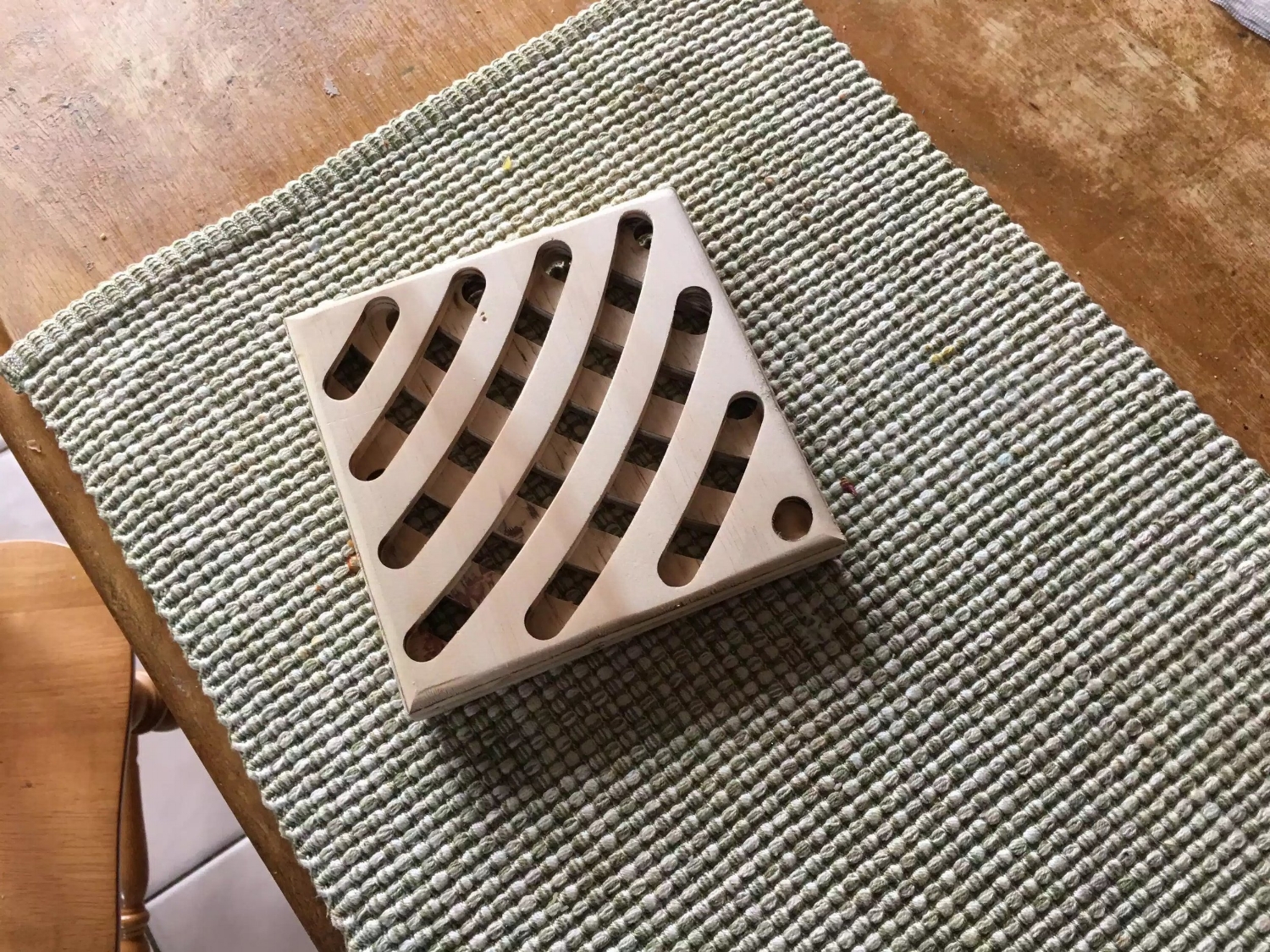
Below are several pictures of the finished prototype, I hope you like.

Frontal picture showing the glasses in there homes, there is about 1” clearance from the glasses to the table-top. Love the dado joint.

Here is the top view, 1/2” gap is perfect.

Here is the side foot, I think this is my favorite aspect of the prototype, really like the curves.
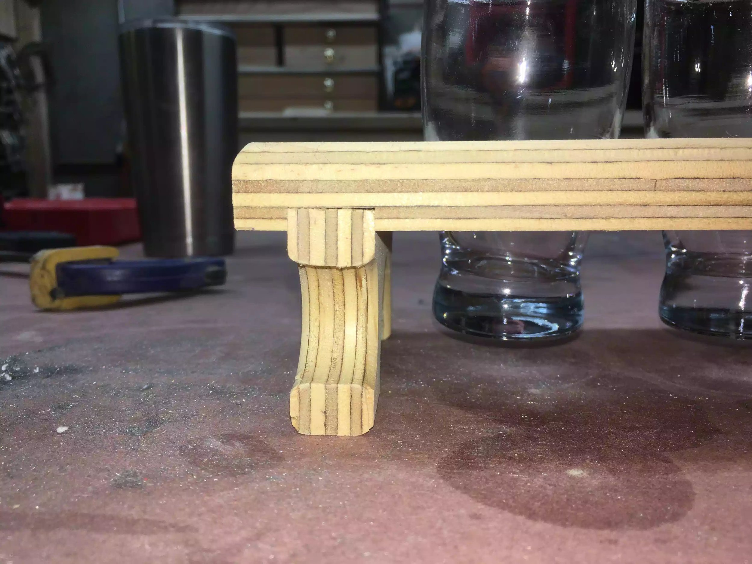
Even in plywood the dado joint looks awesome , imagine what this will be like in the real deal.
I will be starting the build. Hopefully I will catch you guys later.
I have been wanting to make one of these for some time now and I figured now would be a good as time as any, and they make a great gift. My last project was a success but to be honest I am a little worn out making Trivet’s but this is why I love woodworking as a hobby mostly because I can pick and choose what projects to make and when.
In my spare time as rare as that is, I love frequenting local craft beer breweries and when I first went to one about 2 years ago I was amazed at the quality of beer that was being made in the same town that I live, love IPA’s. Anyway craft beer breweries rotate their selection very often and since they do that you are never sure which one to try next and that was when I introduced to my very first beer flight, which is usually a selection of beer samples that are usually 5 ounces and they also arrive on a wooden paddle that holds the beers in place, well that is what I am going to make.
Usually when I want to make a project I have a process that very rarely changes and are usually performed in this order
Inspiration (Research)
Design (Sketchup)
Source Materials
The build
But this time was different I went to the lumber yard at Barney & Carey before I even designed a model. Some of the wood that I wanted to use was species that I never used before and therefore didn’t know how much this project was going to cost me, I am glad that I waited and I was also very surprised at how many great pieces of wood at an affordable rate I could get.
I wanted to get 3 types of wood and they had to be contrasting species so that they would look great next to one another. So I eventually purchased Brazilian sapele, soft maple and walnut.
I also wanted to sell a few of these after they were made and wanted to supply the glasses that would fit into the flight and not leave that up-to the customer, so I went looking for a case of glasses and man are some glasses very expensive, but I had a specific type of glass in mind and eventually found them at a restaurant wholesale business and they were selling them for $2.00 a piece I thought that was expensive until I started looking some more, I could get another similar glass a little cheaper but the shipping costs were not what I wanted to pay and as well were estimated 10 days out. I needed the glass for its dimensions as that is what I will be building the flight around so I eventually purchased the glasses at $2 each and I had to buy a case, so that is what I did. A picture of the glass is below
Below you can see the woods that I purchased and I always sticker them for at least 24 hours so as that they acclimatize to my workshop.

Here are the boards that I purchased at Barney & Carey lumber, the bottom 2 are maple, the next 2 up are Sapele and the top pieces are walnut.

Here is the close-up of the lumber.
While doing some research I came across so many styles of beer flights, some were nothing more than pieces of pallet wood with a few holes drilled to have glasses just sit on them and some other styles were more elaborate that had a lot more work put into them, I decided to make one that had a lot of character to them, that is why I chose to use multiple contrasting species of wood.
Below are some of the features that the flight will have
Wooden Flight will be made of sapele, walnut and maple woods.
The woods will be cut into strips and arranged in a contrasting way so as to highlight the features of each wooden piece.
It will hold 4 sample glasses.
It will be raised up so as that the glasses will be suspended within the flight.
The top will have a round-over profile that will make it nice to the touch.
The legs will also be made of the same contrasting style of woods so as that it blends with the top.
I think the overall dimensions of the flight will be 13” x 4-1/2” x 2-3/4” high.
I did some preliminary drawings on my 3D software and you can see them below, there might be some subtle changes to the overall design but it should look something like the below pictures.

As you can see from the picture the feet will be housed in a groove beneath the flight itself which will provide a lot of stability for all the beer it will hold. This picture also demonstrates how the glasses will be held.

Here is another 3D image of the flight with the glasses removed, the wood colors are indicative of the actual wood I will be using, these images don’t have a grain pattern to them but trust me after its made it will look awesome.
I will start making this project next week at some point and I will keep you posted as to all progress that I make.
Until then take care.
I finally finished my last set of trivet’s and there different because of a couple of reasons.
Made from solid white oak
These trivet’s will be sold as a set of 3
There is 2 sizes in the set a big one at 14-1/2” and the smaller trivet is 7” sq.
I did make a set of plans that I will be making available in my shop soon and the plans detail how to make both sizes.
14-1/2” x 7” x 3/4” (Long Trivet)
7”x 7” x 3/4” (Short Trivet)
Table-saw
1/2” wide dado stack
A power sander , I used a random orbital sander
I used a 1:1 ratio of oil based polyurethane & mineral spirits, I applied 2 coats sanding between each coat with 320 grit sand paper and then finally burnished the trivet with 0000 steel wool.
Here is the completed trivet set.

Here is a top view of the larger trivet

Here is a top view of the smaller trivets

Here is a view of the bottom of the trivet set

Here is the bottom view of the larger trivet

Here is a view of the bottom faces of the smaller trivets, I actually like this side of the trivet, but I guess I like the top face more.
I will be making the plans available soon and these trivet set’s will also be available in my Etsy store and my shop here, I hope to have all these items posted in the next few days.
Thanks for reading and see you next.
I have to say that I am definitely love making trivet’s although they may not be a money maker that I hoped for but I will leave them in my shop just in case someone actually comes across them.
Anyway I am moving away from the router made trivet’s just for a change and will be making this trivet on my table-saw equipped with a dado stack. The trivet actually don’t take that long to make but they do take more time sanding and applying finish to them mainly because of the drying time involved. The larger trivet is more than twice the size of the last project I did.
Anyway this is the Process, need to apply finish but that is for another days work.
Purchase the lumber & Sticker it overnight
Ripped the wood to its final width
Crosscut the trivet blanks on my miter saw
Router Table Time
Design & Spacers
Dado stack time small trivet
Larger Trivet
Sanding & More Sanding
I purchased the lumber at the same place I bought the red birch for the last trivet’s I made from at Barney & Carey Lumber located in Avon, MA. but this time I purchased white oak for my current project, I have used red oak in the past but I purchased it big box stores and let me tell you the quality difference between the two is huge.
For the lumber to dry properly, you’ll need to sticker your pile. Stickering refers to the use of narrow strips of wood – typically 1”x 1” – between the layers of lumber to allow adequate air flow. For best results, the stickers should all be the same length (the same as the width of the pile) and rot- and stainfree (to minimize staining your lumber). In a perfect world, the stickers would be dry, but billions of feet of wood have been stacked using green stickers created in the board edging process with perfectly adequate results.

I sticker-ed the wood here using some scrap wood to separate the two boards.
So my first step was to rip the wood to its final width and I figured it better to do this before I cross-cut the wood into their respective trivet sizes, anyway its better to rip one board than 20 of varying sizes as you are removing or lowering the percentages of error.
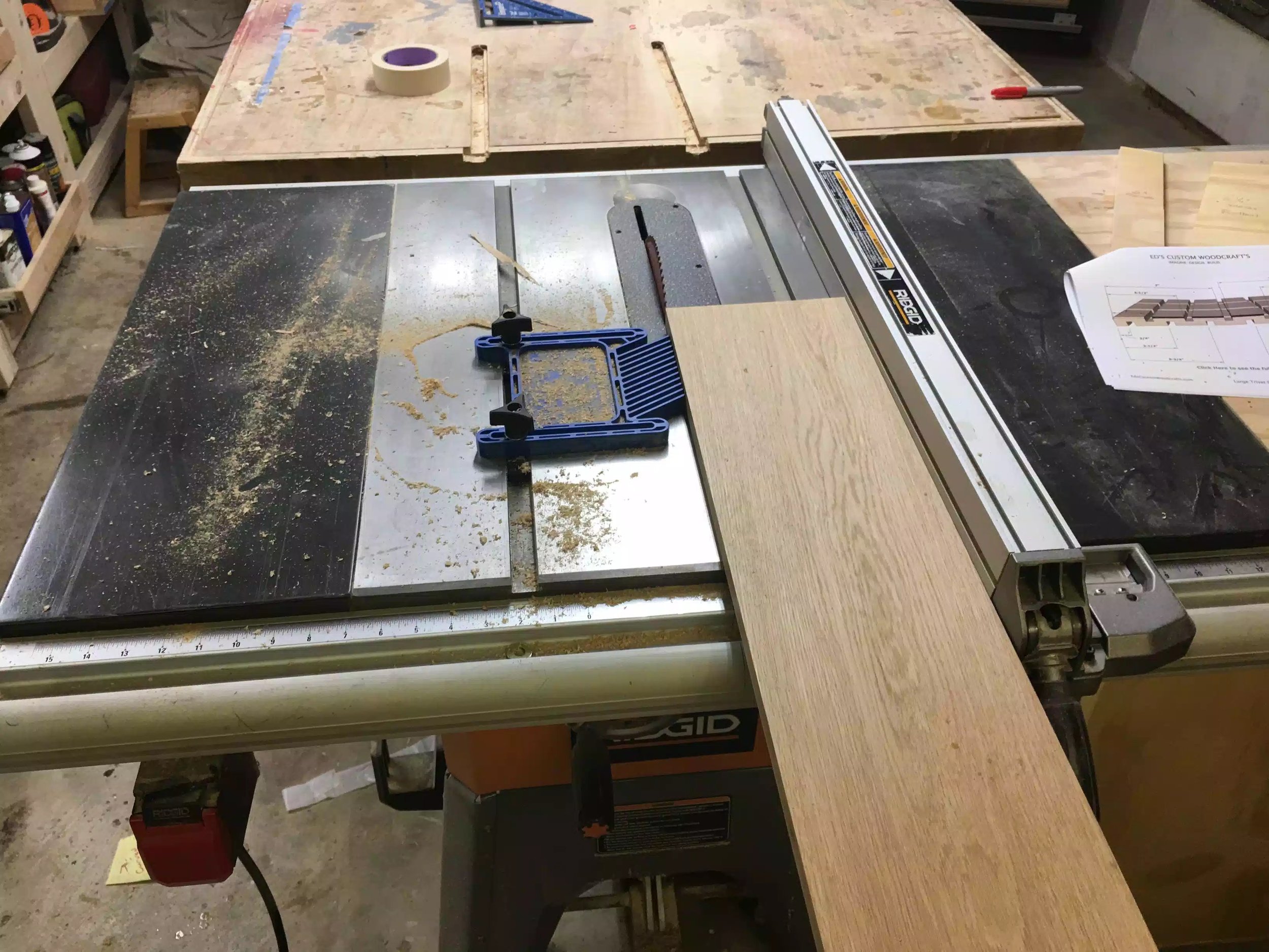
I used my feather-board to make sure that the board didn’t move away from the rip fence, I also used a rip blade for this process.
Next step was to cut the trivet blanks and I used a set-up on my miter saw station where I used a stop block but because I was making two sized trivet’s I made 2 sized spacers, so placing the the stop block I measured the distance for the larger trivet and cut a spacer to that size, then measured the distance for the small trivet and created another spacer block to that dimension, below you can see some pictures of the process, this makes it very easy to repeat cuts and makes the operation go a lot smoother and removes the need to measure every single trivet that needs to be cut.

Here you can see the oak sitting on the miter saw deck and the spacer block is establishing the positive that I need to make all cuts the same size.

Here is a image of the stop block and its nothing more than a scrap piece of ply that I cut to make sure that all the large trivets are the same size, I also made another one for the smaller trivet. Not the metallic production stop this never moves and I can swap out the 2 spacer blocks dependent on what size trivet I am cutting. It worked like a charm.I also label each spacer block so I wouldn’’t get then confused.
The next phase of the build was to add a round-over to the trivet on all faces I figured this would be a lot easier to do while the the trivets were still blanks and did not have a ton of grooves and dadoes for the router bit to get stalled on. So using my router table with a 1/4” round-over bit in the router I made a couple of passes to remove all the sharp corners.

Here is the router table with the but installed.

Here is a close-up of the round-over bit.

All 3 trivet blanks have the round-over now and really feel smooth to the touch.

Here is a close-up shot of the round-over, looks and more importantly feels great.
I meant to say that before I brought the pieces to the router table I wanted to make sure that I put the trivets in sequence as to how they were cut from the board that way I was maintaining the boards natural grain direction and making it look really nice. Below you can see what I mean, I also marked the best face for the top of the trivet.

Here is the boards with the grain direction flowing right through the board, I also marked this face as the top of the trivet.
I came up with the design on my 3D software Sketchup and I actually made it in the last batch of trivet’s I made and thought that this design would look really nice if it was a lot bigger, I made a quick and dirty set of plans to follow so as that I put the grooves in the right places.
To help me all the grooves and dadoes that made up the design of the trivet I needed to make some spacer strips so as that I could repeat easily on every trivet.

Here are the spacer strips that I would use to align the table-saws rip fence to the trivet, I also marked each spacer width on the board so as that I didn’t use the wrong one.I used 6 spacers in total with measurements of 3/4”, 2”, 3 1/4”,4-1/2”, 5-3/4'“ and 7”.
To make the trivets I decided that I would use my dado stack. The trivet is not that hard to make but it does require a decent amount of concentration as it is easily screwed up. The lattice design is eventually created by rotating the board and using the spacers in designated areas. I was working both faces of the trivet. I will try my best to give accurate step by step below.
Place a 1/2” wide dado stack into the table-saw and raise it 3/8”. Since I am working on the small trivet I start with the 2” spacer strip as seen below. Run the the trivet blank through the Dado Stack which I will be calling DS from now on.

Here is the 2’ wide spacer strip to position the fence 2” away from the cutting edge of the DS.
STEP 2:
Here you can see the trivet positioned to cut the 1/2” wide 3/8” deep groove, once one side is rotate the trivet 180° to catch the other side. Now you will need to rotate the trivet so as that you can position 2 more grooves running perpendicular to the grooves you already made

Here you can see the trivet positioned to cut the 1/2” wide 3/8” deep groove, once one side is rotate the trivet 180° to catch the other side.
Now you will need to rotate the trivet so as that you can position 2 more grooves running perpendicular to the grooves you already made. After this is done you trivet should look like the picture below

After step 2 your trivet will look like this, you will have 9 squares measuring 2”x2” and they are all on the same face (this is the top)
Next we move onto cutting the grooves on the bottom face of the trivet, this is what determines the lattice style, if you dont like my spacing you can always use your own imagination to come up with your own design, anyway
With the 1/2” dado stack raised 3/8” high we are basically going to run grooves on the bottom side splitting the squares on the top in half but from underneath the top face, confusing I know but the pictures will help.
So using the 3/4” spacer to determine the distance from the blade to the rip fence we will run the trivet through the blade, after you run the trivet through the first side rotate the work-piece 90° and do the other 3 sides

Here is the orientation of the trivet being run through the blade, the groove will be 3/4” from either edge and what this does is places a groove directly under the 2” x 2” squares on the top

This is what the trivet should look like now, all the outside edges should have a slot cut in them.
This is the final step in cutting the grooves on the small sized trivet.
Using the 3-1/4” sized spacer to set the distance from the fence to the blade, this will center the dado stack in the middle of the work-piece to place one more groove.

Here is the 3-1/4”spacer

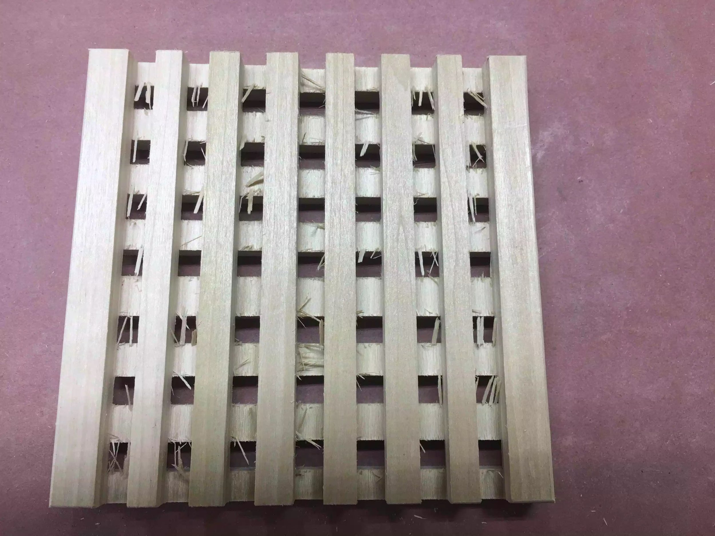
Here is the finished trivet, still need to sand it as there was a lot of tear out
Other than sanding the trivet down the smaller of the 2 trivets are made, I need to do a lot of sanding as you can see there is a lot of tear out, I need to figure out a way to reduce the amount of tear out as this will take a lot of sanding to make nice to the touch.
The larger trivet is 14-1/2” long x 7” wide and is also made using the same lattice pattern as the smaller trivet, my goal is to sell these as a set of 3.
Using the 2” wide spacer block to determine the distance of the blade from the fence I ran the board through the blade along its length to establish the 2” wide squares on the top face then a swung the board to its other side and repeated the cut, creating 2 grooves running the length of the board .

Here is a picture of the 2’ wide spacer to determine the distance from the blade to the rip fence, after the rip fence is clamped I remove the spacer block and run the board through.

I forgot to take a picture of the work-piece with just the 2 long slots cut, just disregard the under side cuts, that will be covered later.
So using most of the spacer blocks I start cutting all the cross grooves on the bottom of the trivet creating the lattice effect for the trivet.
I started with the 3/4” spacer and got all for sides of the bottom of trivet, then moved onto the next spacer which is 3-1/4” wide and again completed 2 across the grain cuts at each of the ends, next spacer was 5-3/4” and again I cut 2 across the grain grooves on each end and finally I used the 7” spacer and this located the center of the trivet and you should have a trivet that looks like this below.

Your trivet should look like this all the grooves in this past step were on the bottom face of the work-piece.

Here is the completed bottom face of the trivet, I did however make an error I used the 7” spacer on the bottom and I didn’t need to that spacer was only to be used on the top but it turned out OK and I left it, that is why the middle of the top face of the trivet has that longer rectangle instead of 2 squares
Now that all the grooves were cut on the bottom of the trivet I needed to make the grooves that set up the 2” squares. As I mentioned above I made an error when I was doing the final cut on the bottom of the trivet I used he 7” spacer and I should not have because that spacer was for the top side, so as it turned out that I have bigger squares in the middle of the trivet and not 2 the same size as the rest. I determined that it actually didn’t look that bad and left it as a design element.
So lets move on
I started milling the top of the trivet and I started with the 2” wide spacer and cut the grooves on each end of the board, then move onto the 4-1/2” spacer and cut 2 grooves on each end of the board and that is it. If i had followed my plans I would have used the 7” spacer next but since I already used that on the bottom I could not use it on the top as it would have divided the trivet into two halves and I didn’t want that .

In this picture you can see the grooves left by using the 2’’ wide spacer when you turn it end fro end you get both grooves without re-measuring and that is said for all spacers except for the 7” spacer which was used to locate the middle groove of the work-piece.

Here is the plan of what the trivet should have looked like but instead we have whats below, I don’t think it looks bad at all, sometimes mistakes look good.

Here is the finished large trivet.
So after all the table-saw work was finished I needed to do a lot of clean up work on the trivet’s as there was so much tear out , if your not familiar about tear out this happens when you are cutting wood with machines or by hand and what happens is that unsupported wood fibers blow out, I found an interesting article in Popular Woodworking that describes tear-out.
I need to do some more research and try and come up with a solution that will prevent large-scale tear out. Below are some pictures of the tear out that I had on my trivet’s.

Here is all the tear out I had on the underside of the trivet. All of the broken wood fibers is what tear-out looks like.

Here is a closer look at the tear out on the bottom face.

Here is the tear out I had on the top of the trivet
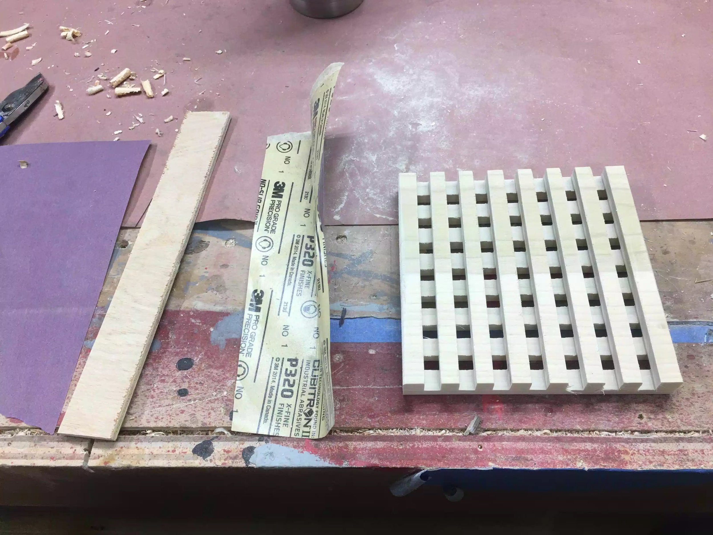
This tear out will be easily removed in some locations and other areas will require a little more work. I found the tear out really bad on the underside of the trivet especially in slots that were cut, so to remedy the problem of sanding in tight quarters I made some home made sanding blocks, these are nothing more than scrap wood, but the wood had to less than 1/2” thick as that is the width of the grooves we cut, then I used various grits of sanding paper to smooth out the edges.
The top and bottom faces of the trivets were easily sanded as they were flat and I didn’t have to contend with the grooves, I used my orbital sander moving from 120 grit all the way up-to 400 grit and its very smooth now.

Here are my aids, 3/8” thick scrap piece of wood that I used to wrap the sandpaper onto and moves in and around all the grooves with ease.
Here is what the trivet looks like now after a decent amount of time spend sanding them, is it done ?? I ask myself and I say no because all the over lapping milling marks left behind by the dado blade are not totally gone so I will need to return and do more, but as you can see the difference in the before and after is a big difference.

Before sanding

Before Sanding

After sanding, this is the bottom side of the large trivet

After sanding on the top face of the trivet.
So after all the sanding done today there is a huge difference but before I go into production mode I need to figure out some solutions to some of the problems I encountered making this set.
Need to solve the tear out :- I might try cutting reducing the depth of cut and not taking out all 3/8” at one time, also considering alternating the with the grain and against the grain cutting, if I do all the against the grain cutting first hopefully cutting with the grain will also reduce the tear out.
Making sure I font repeat the mistake that resulted in a groove being placed in the wrong place, this cut have been a costly mistake but I was lucky that it didn’t ruin the trivet, this one is easy slow down and follow the plans .
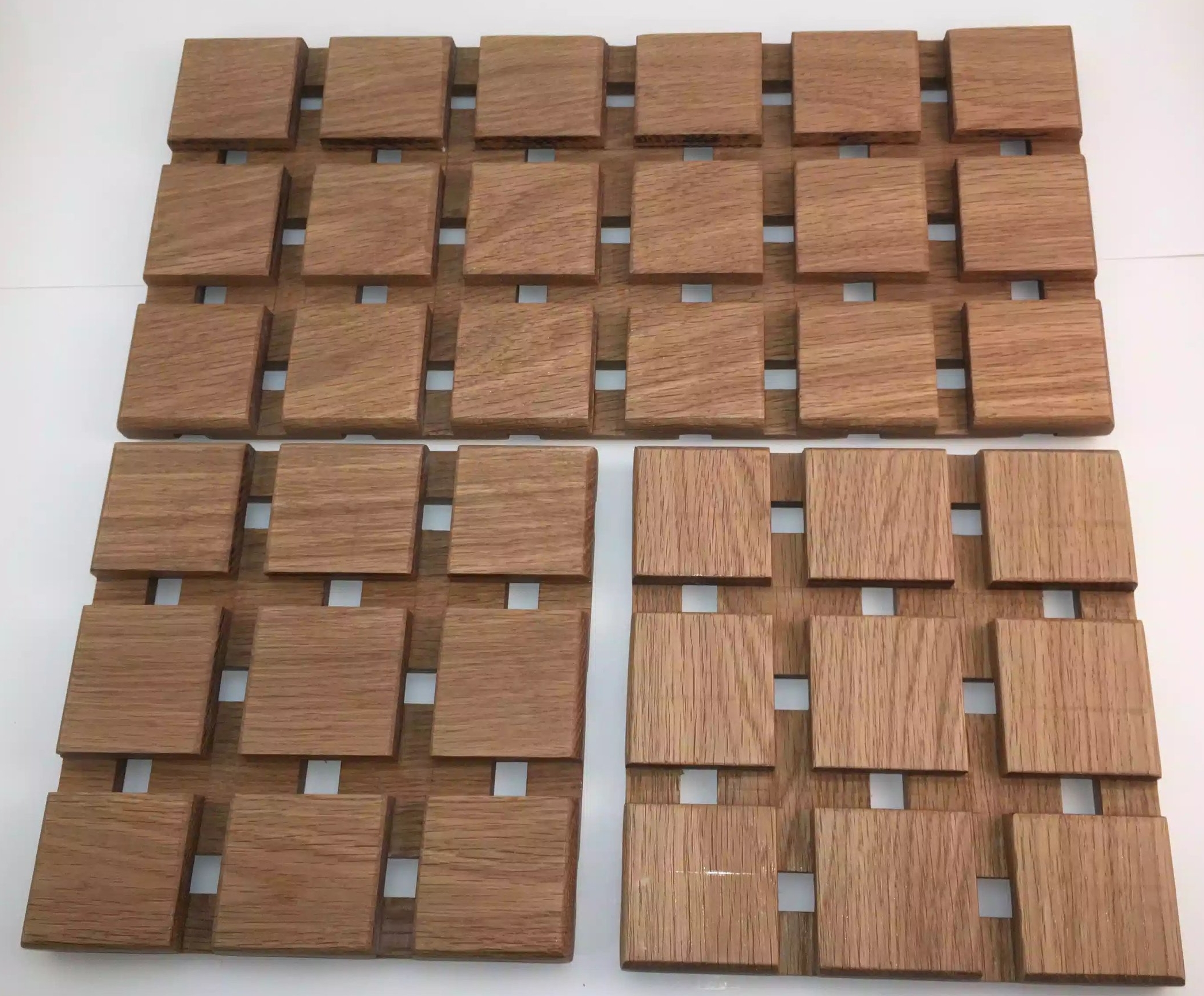
Below are the 3 trivets that I made using this design and I have to say that they look great and especially like the white oak that I used but to be honest I like the red birch better, but the red birch had a lot of wood burn where as I didn’t get that with the oak.

Here is the finished set, there is almost 30” of space to hold hot plates and casserole dished or even a Thanksgiving turkey

You can arrange them any number of ways this is just another example.
NEXT:-
I need to apply the finish to them but to be honest this is a rinse and repeat from the last batch of trivets that I made using 3 coats of 1:1 ratio of oil based polyurethane and mineral spirits and after that has dried I will burnish them with very fine steel wool.
Hello everyone,
I know that its been little while but better late than never, I am excited to announce that for the first time since I launched this site I am able to bring you my very first physical product line that everyone can use at home, as a gift, or just as a decorative table ornament that can be used with all the special holidays that are coming up.
I also want to inform that I am still keeping the site with Squarespace but I have partnered with Shopify to facilitate all my fulfillment services, so don't worry when you purchase a physical item on my site and are transferred to another site for Checkout. Right now all my digital plans will still be handled right here.
Since my router trivet jig generated so much interest among all you makers out there, I am giving this plan away for free, just head on over to the link below and download the plan absolutely free.

Food for thought
So over the last few weeks I have putting all of my efforts into trying to come up with ideas of projects that would enable me to make a side income, after all woodworking is somewhat of an expensive hobby.
As you can probably surmise from my recent blog post that I have been working with trivet’s and my main reason for this is because I intend on (and have actually started) making several designs that I hope to sell on my Etsy page and in my store here on my site. What has actually been taking so much time is figuring out best shipping practices, my primary reason for never doing this line of business was because I always thought that shipping in the United states was a terrifying ordeal because of all the intricacies involved in setting up. When all the time right under my nose fellow Etsy store owners were doing exactly that making small flat rate sized items for sale and distribution within the United States and beyond.
So in the coming weeks and months keep and eye out as to what is happening on that end oft he business, I am also doing more research in setting up a e-commerce provider that can help me with setting up the sales & shipping aspects of what I am trying to do. I currently use Squarespace as my website host and I don’t want to change that as I believe they have the best “value for money” in regards to making your own website and they have awesome templates that enable you to make a website no matter what type or style of content you will be creating.
What I am ultimately looking for is to have multiple small revenue streams that enable me to make small projects and also looking for a little income stream that can then be absolved back into the business, enabling me to buy better quality tools, buy better quality wood and ultimately creating higher quality projects that are worthy of people to purchase, people such as yourself.
So over the next few weeks I will be spending my time creating some products that I will sell on Etsy and then hopefully after a trial run I will also stock my shop here at www.edscustomwoodcrafts.com
I recently received another Daily Top 3 Award on my online workshop where I currently have a membership with www.lumberjocks.com.
I received the award along with 2 other makers that also made woodworking projects. My award was for the Trivet Router Jig that I made for the shop. I have included links below for the project.


Here is the trivet jig that I made.
So as of late I have been playing around with the idea of selling and shipping products on my site, but in the past I was really hesitant because of the costs associated with shipping and trying to determine how much to charge for said projects.
That was until I came across a show on YouTube about making and batching out certain projects for sale with minimal cost and time constraints. So that is how I came up with making Trivets because of a couple of reasons.
Small (Low shipping weight)
Can be made with a variety of woods
Can batch 10 or so in a day (without applying finish)
I already had an Etsy shop to sell from
I would love to take credit for this jig but unfortunately it wasn’t me, I came across this jig online at www.rocker.com , the jig’s concept is really easy to comprehend. It’s basically a trammel on a base, the base has 2 fences that hold the trivet blank and you adjust where the slots are cut with spacer blocks. Ill explain in more detail in a later part in this blog.

Here is the completed jig, its basically a base that has 2 fences that form a 90° corner where the trivet gets positioned, and held in place with the fences.

Here is a picture of the jig with the trivet blank positioned between the fences, I also used self adhesive sand paper to help keep the blank positioned while using the router.
Here is the jig in use, you can see the router attached to the pivoting arm which is how I achieve the curved grooves in the trivet.

Although this is a plywood prototype of one of the designs I will be using, I am very happy with this design.
Source Rockler.com
The trammel jig is fairly easy to assemble and, while it doesn't alter router's cutting radius, it allows you to make repetitive cutting patterns very simply. The jig is really simple to build. Start with a 22"-square scrap of 3/4" plywood or MDF, and draw a diagonal line connecting two corners. Cut a 6"-square trammel support from 1/2" scrap and bisect it with a pencil line. Fasten it to the base with glue and brads so the outermost corners of the support align with the edges of the base and the pencil marks of the two jig parts line up. Now rip a pair of 1/2" by 2" fences, cut them to an overall length of 15-5⁄8" and miter-cut one end of each to 45°.

Completed trammel jig (stock photo)
Once you've put the mitered ends of the jig fence together against the support block, nail them down to secure them to the base. Butt the fences against the support piece so the tips of the miters touch. Make sure they form a square “pocket” for the trivet blanks to register against before nailing the fences to the jig base. Line the “field” area inside the fences with sandpaper attached with spray adhesive. Later, this will hold the trivets stationary as you rout them. I left the base’s outer corner bare where the trivets and spacers don’t reach it.

After mitering the corners of the fences to 45°, pin them in position and making sure everything lines up using a square. (stock photo)
ADDING THE TRAMMEL
Draw a layout line 12" from the center-line of your bit to establish the pivot point of the trammel. The trammel is a scrap of 1/2" material cut 6" wide and 20" long; this width fit my router base nicely. If your router has a wider base, change the trammel width to suit it. Set the router near the trammel’s end to mark mounting holes for screws, as well as to establish where to bore a clearance hole for the router bit. Mark the trammel carefully with two layout lines: one identifying the center-point of the router bit and a second drawn 12" back from this line, before making the bit clearance hole and fastening the router to it.

Attaching the trammel to the router (stock photo)
Slide the trammel along the support block until the router bit touches the outer corner of a trivet blank to set the position of the jig. You’ll need one of your 6"-square trivet blanks to mount the trammel properly on the jig. With the router bit installed, set the trivet blank in the corner formed by the fences and balance the trammel on it and the square support block. Slide the trammel along the support until the inside edge of the bit just kisses the outer corner of the trivet
Positioning the router in order to find the pivot point on the jig (stock photo)
Use the dowel's pivot point line to find where you can bore a dowel hole to complete the trammel. Make sure it lines up evenly over the support before boring a 5/16" dowel hole through the trammel and support — right into the base. Center this hole on your 12" layout line drawn previously. Now insert a 2" length of 5/16" dowel to engage the trammel’s pivot action. You’re nearly ready to start routing trivets, but first, make up 14 spacer strips from 1/2" scrap. Mine were 3/4" x 14".

Drilling the location of the pivot pin (stock photo)
Making your first cuts on the trivet face using a pair of spacers along the jig fences and cutting a little deeper than halfway through the blank in the first slot. Start the router and make your first cut, milling to final depth in two passes. I used a 1/2” up-spiral router bit — but any sharp straight bit should do fine. Swing the router clockwise or counterclockwise — either works fine, but keep the trammel pressed down firmly against the trivet blank to prevent it from shifting.

Begin routing the design (stock photo)
Continue adding and subtracting spacers and feeding your router clockwise and counterclockwise to make further cuts, but keep the trivet stationary as you pivot the router. Once you complete the first cut, pull the trivet forward, insert another pair of spacers and repeat for the second, longer “swoop.” Continue adding spacer pairs between subsequent cuts until you reach the other corner of the blank. Now flip the blank over, give it a quarter turn to establish the “X” pattern and repeat the whole routing process. This time remove one pair of spacers after each pass.

Adding spacer strips to maintain equal gaps between the grooves. (stock photo)
Flip the trivet and give it a quarter turn to make an "X" cutting pattern on the second face, continuing to cut them in the reverse of how you made the first side. In minutes, you’ll have your first trivet knocked out and be on to the second. Sand away any bit burn marks or fuzz, and round over the edges

The waffle pattern is coming to life. (stock photo)
THE above step by step guide is taken from the Rockler.com article as well as all the pictures, but below is a trivet that I made and looks OK, it will look even better when I actually get to use some really nice wood and not the plywood prototype that I used below.

Not too big and not too small, this prototype will look great in oak or ash.
Adding a round-over to both sides of the trivet really feel great to the touch and doesnt look too bad either.
Love the dimensional aspects of this little project.
I still need to do some research on making these and eventually with a bit of luck will be able to sell them in my Etsy store… I will also be making FREE PLANS for the jig once its completed I will posit it in my shop, don’t worry I will post when their available.
Thanks for reading, and I will catch you all again soon.
So I needed a little project to keep me busy and I needed to use up some scrap wood that I had lying around. I was sitting at dinner one night and noticed that all the trivets looked terrible and some were even broken, so I went on YouTube and finally found an easy way to make them using a table-saw and dado stack.
The Wood
Miter Saw
The Trivet blanks
A little Layout
Cutting the Grooves
Adding a Round-Over on the Router Table
A lot of sanding
All finished
Since I wanted to use up some scrap that I had around I used a piece of 1x8 poplar that I could get about 9 trivets out of. I wish I had some 1x8 oak as that would of been a nicer trivet, but maybe in the near future I will make some trivets for Christmas presents.

Here is the piece of poplar that I used.
Usually I use the miter saw a lot for a project but I only wanted to cross-cut the board to around 18” as I wanted to do a trial run making 3 trivets and see how they turned out.

Crosscutting the board at my miter saw station.
So after cutting the piece I took it from the miter saw to the table-saw and ripped the board to its final width.
I took out my cross-cutting sled because I usually get more accurate cuts from it and set-up a stop block and cross-cut the board into 3 blanks that were exactly 6”x6” square

Here is my cross-cutting sled is not fancy but it’s dead on accurate. You can also see the stop-block which is nothing more than a scrap of plywood clamped with the sled fence.

Here is the 3 blanks all dimension-ed and ready to be turned into trivets.
I needed to do a little layout on one of the trivets to make sure all my dimensions were correct, so I took it to my bench and drew some layout lines where I was removing wood.
Measure over 3” to find the center of the blank and strike a line, then measure 3/16” to the left & right of that line so as to center the 3/8” dado stack to the work-piece.
Finally measure 3/8” on the wood thickness (as it is half of 3/4”wood thickness) so as that I new where to position the dado stack in the table-saw
Now that I had marked up one face I needed to turn the board 90° and do the same on that side that is what creates the waffle pattern I am going for.

Here are my layout lines on one of the edges. All the “x” represent where the grooves will be run.

Here you can see the dado stack measuring up-to the 3/8” line on the blank edge.
Here is where it will get tricky in how to explain this process. Using a 3/8” thick dado stack in the table-saw I needed to cut the 7 grooves on each of the marked faces which will give me the waffle pattern design that I want. This is my first time making trivets lets alone doing repetitive groove cuts in such a small pirce of wood, but I am happy with the results, practice makes perfect. One more thing I experience a lot of tear-out doing this and it left a decent amount of sanding after.
Here is my attempt at detailing the step by step process.
STEP 1. With my 3/8’ wide dado stack center on the work-piece I run it through the blade, which results in a centered groove. As you see in the following pictures some of the cuts are made with the grain and others against it which is what makes the waffle pattern.

Using my center-line I ran the stock through the 3/8” wide dado stack

Here is the center groove
Using the groove that I just made in the center, I re position that groove on the blade and use a spacer block which is 3/4” and position it beside the cut groove and line my table-saw fence against the spacer block and then move the work-piece over until it reached the rip fence. This step can gut 2 groves either side of the center by simply turning the workpiece 90° after each cut.

Here is the spacer block against the fence, when I remove the spacer block and move the work-piece against the fence it will center the next 2 grooves.

Here you can see the work-piece butted up to the fence and ran through the blade, once this is done I rotate the piece 90° to get the other groove.
This is what you should have, 3 grooves equally spaced.

After repeating step 2, two more times you should have this. 7 grooves all running in the same direction, and for the most part equally spaced.

Here is a edge view of what your work-piece should look like.
Using the center line on this side, run it through the blade which is still at 3/8” wide & 3/8” high, you might need to make a couple of passes until you remove enough material to reveal one groove where you can see the waffle pattern below. After this step you should have what looks like below

Waffle pattern coming to life after cutting the center groove.
As we did in Step 2 above we need to repeat that process to define all remaining 6 grooves using the spacer block and the rip fence method I used in Step 2. You should now have a work-piece with the waffle pattern visible, although in rough shape because of all the tear-out.

With 3 grooves cut, your piece should look like this, only 4 more cuts to make.
Here is the final waffle pattern, there was so much tear-out that I thought that I was doing something wrong or my dado stack wasn’t sharp. Anyway we clean this up later.
To remove all the sharp edges on the outside edges of the trivet I used a 1/4” round-over bit in my router at the router table and eased some of the edges.

1/4” round-over profile bit in the router table.

I’m not sure if you can see the round-over profile as it is very small, but it did the trick. I will also be using several grits of sand paper to clean it up more, especially on the inner grooves that the router table cant reach.
To be honest the most time consuming part of this project is all the sanding that needed to be done, there was so much tear-out on the inner grooves because the wood was un-supported going through the dado stack that it created a mess, so I used a piece of sand paper and wrapped it around a 1/4” thick piece of plywood to fit inside the grooves, I also used a chisel to remove some of the stubborn wood fibers.
After using the sandpaper I turned to my random orbital sander to sand the top / bottom sides of the trivet to make it inviting to the touch.

Here is what I started with when beginning to use the sandpaper.
Here is my solution to sanding in between the grooves. Some various grits of sand paper finishing with 320 grit and a piece of 1/4” plywood scrap. I wrapped the paper around the plywood and went to town.

Here is the sandpaper doing the trick

Here is the finished trivet, a great improvement over what I had started with.
Well I set out to make 3 and that is what I got done today, I gave the 3 to my mother in law and she was happy. These make a great little present, and the holiday season is coming up. I must say this was a fun little project and the possibilities are endless with the style options. I am actually thinking of making a jig that I can use with my router to do curved grooves, below is a few pictures of the threesome that I made.

Awesome project and a nice little item at the end.

Whats useful is that you can group them together if you have a large item that your table-top needs protection from.

Well thanks for reading and I hope to catch you again soon. I am in the process of making plans for these exact trivets and I will post them in my store as soon as they are completed.
I recently received an award for the Portable Sharpening Station from www.lumberjocks.com
If you would like to read all the project from beginning to end, I created a blog series that can be found here. If you like the project that much I have just made plans available for the project here.
Thanks Lumberjocks for supporting everything that I do, and I am always appreciative of any and all recognition that I receive.


The completed Sharpening station.
Today I finally got to finishing this project all I needed to do was to add wooden plugs to the countersunk screw holes for the base and apply a urethane finish to the entire sharpening station.
I usually have some oak dowels lying around the shop but for the life of me couldn’t find any so I needed to make my own which is very easy. I used a 3/8” plug cutter in my drill press and since I had some oak scraps lying around from this project I used it. Below you can see some pictures of the process.
Step 1 : Cut the plugs on the drill press
Step 2. Added some glue and hammered the plugs into place
Step 3. Was to flush cut the plugs to the surface.
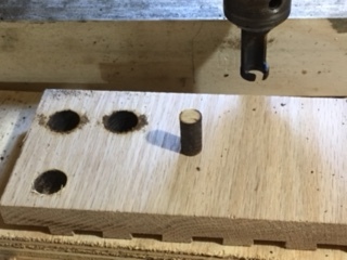
Cutting the plugs on the drill press.

Here is a close up of the plug cutter.

Here is the protruding plugs that needed to be flush cut.

Finally using my flush cutting saw, I trimmed the excess off.
Now that everything was done all that was left was to apply a finish, the finish I wanted to use was Minwax Poly-Crylic but by big box store didn’t have any so I choose an alternative water base polyurethane and I applied 3 coats.

Here is the last of the 3 coats, applied to the top, still wet.
Here is a before picture , this is before I applied the finish.

This is after the finish has been applied, I love how the box joints pop.
All that is needed now is to wait for the finish to dry, but here are some final pictures. I love how handy this station will be and I should have made it a long time ago, everything that I need to sharpen my tools is now in one place just the way I like it.
This concludes my blog on this project, I hope you have enjoyed reading about this project as I have enjoyed making it. I will be releasing plans for this in my shop as soon as I have a chance in putting them together.
Until the next time I’ll catch you later.
This station is a very comfortable height for me to work on, although I might have gone over-board in its design it is extremely functional.

Here is my Veritas MKII honing jig being put to good use.

I really like the contrasting oak plugs that I used and also really enjoyed making the pulls, which I made from solid ash.

I really love having everything that I need right at my finger tips.
So today I got so much done and the project is almost finished all I have to do is apply a finish to the station and add wood plugs to the screw holes and it will be ready.
Here is what I got done today:
Made a leather strop
Remade the base
Made wooden pulls
One final item that I needed to make for the sharpening station was a leather honing strop and I found a YouTube video that Paul Sellers made regarding making one, he used a scrap piece of wood and some leather that I purchased at Woodcraft.
Since I had some oak left over from the lid what better use for it than to make 2 leather strops, I cut the oak to the same size as that of the diamond sharpening stones, 8”x3” and I used double sided tape to adhere the leather to the oak.

Here is the honing leather and honing compound that I used, you can find more details on woodcraft, just click the links. But here is all the materials I needed to make the strop’s.

Here are the 2 pieces of oak that I used for the base of the strop.

Next I cut the leather to size using a box cutter.

I added the double sided tape.

Now I have 2 nice honing strops and it only took 5 minutes.
When I was looking at the base I needed to make one recess for a different type of honing guide, I really didn’t like the look of the recesses that I made previously so I just remade the base and added the extra recess. You can see the pictures below, I remade the base the same way by drawing layout lines of the size of the recesses that I need, used my palm router to route to the line and then cleaned it up with some chisels and now it looks much better.

Here is the new base with the added recess for an eclipse stile honing guide.

Here is the new base installed and looks a lot better,

So here is most of my accessories in the box, still need to figure out a method for housing my diamond plates.
I needed to make 2 handles for the sides in order for me to carry the station around easily as it is heavy.
I originally made these pulls before for my Drill press cabinet that I made, I designed the pull on Sketchup and then made a bunch of them when I was making the drill press cart, and of course as usual I couldn’t find them, so I needed to make some more.
I had some left over ash from the drill press project that I used and made like 6 handles out of 30 inch piece of ash.
I used 3 router bits in making them, 1/2” Cove bit, 1/2” round-over bit and finally a 1/4” round-over bit. You can see the pictures below. I also attached my original project where I went into more detail on how I made the pulls, check below.

Here is my ash blank, I started off the process by routing the cove on the back side of the handle.

I made several passes with the cove bit, raising the bit incrementally.

Here are the 3 bits that I used firstly on the left is a 1/2” cove bit, middle 1/2” round-over, right is a 1/4” round-over.

I finally used the 1/2” round-over to add a profile to the top of the handle and then used the 1/4” round-over to the pull.

Here is a layout of what router bits and where I used them.

So here are the 6 pulls that I made from that one piece of ash, its so much cheaper doing your own pulls and are totally customizable
All that was left was to secure them on to the sharpening station, all I did to attach them was to center the pull on the center of the sides pre-drilled 2 holes to receive screws into the handles
Here is the pull attached.
So the project is almost complete and all I need to do tomorrow is to start applying the polyurethane finish and adding some wooden plugs to cover up the screw holes located near the bottom.
Below is where I left the project today and took several pictures to display it.

The sharpening station is more or less finished, I need to purchase 1 or 2 more sharpening stones .

Here is a frontal shot

Here is the inside

Other than the blemish in the recess I think it looks great, its only a shop project so it will get dinged up for sure and wont look any better than this in a short amount of time.
Need to add wooden plugs to cover up the screw holes, Ill probably use oak.
Finally I need to start applying the finish, probably 2/3 coats of Polyurethane.
Thanks for looking, catch you soon.
Today was all about the recesses that I needed to create for the sharpening stones and to be honest there was a decent amount of layout work to be done and maybe 20 minutes of me actually using my router. I gone to great detail explaining the how and the why of the steps that I took.
Materials Needed
Laying out the measurements for the template
Drill Press
Template Cut-outs
Dry run
Router time.
Recesses all done
I decided to use 1/2” thick MDF (Medium Density Fiberboard) for the template because of a couple of reasons, its very flat and easy to mill. I went to my local Big Box store and purchased a 2’x2’ project panel and cut it down to the size I needed.
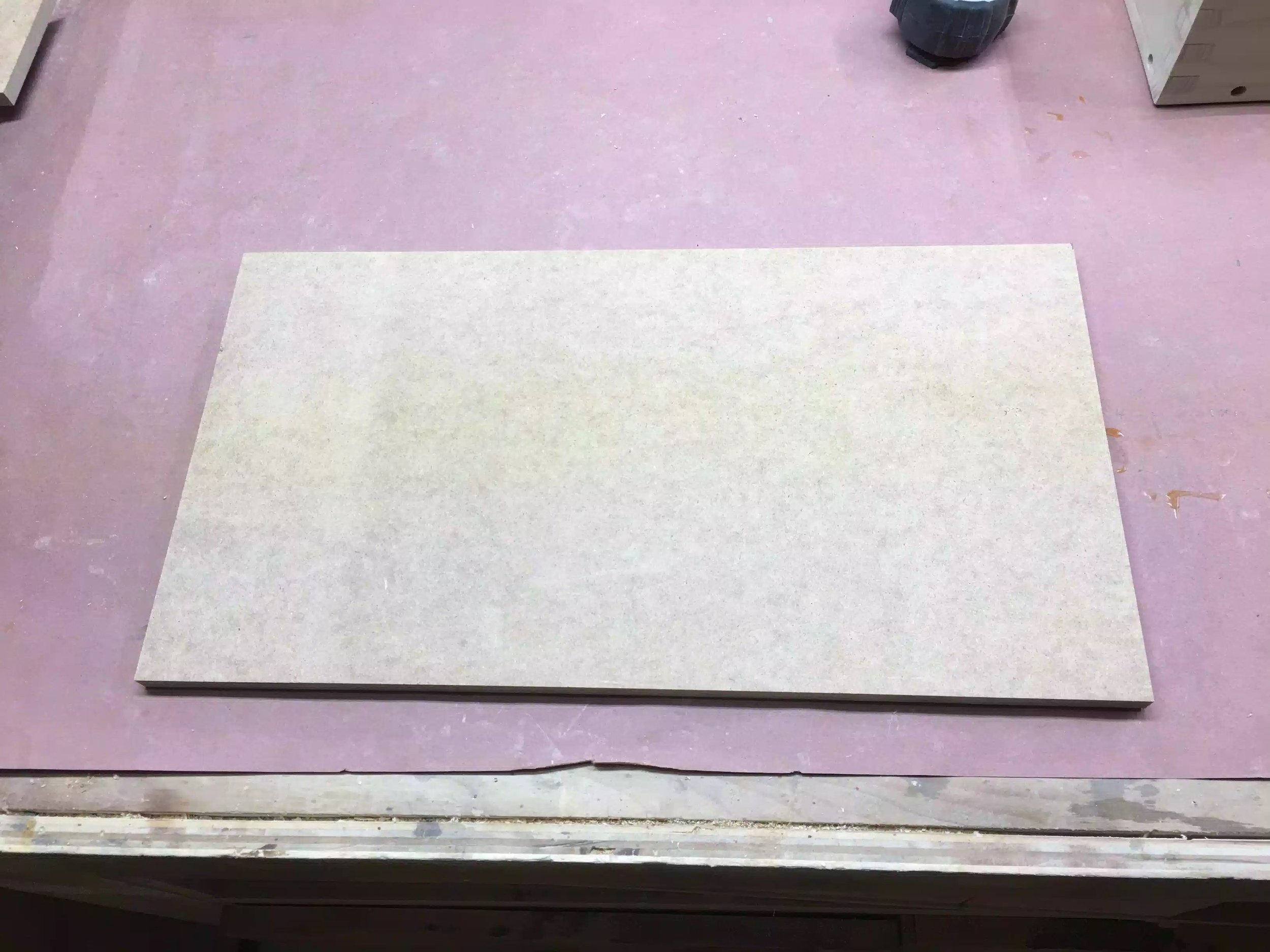
Here is the project panel cut to size, before I made all my layout lines
The longest part of this whole part of the project was this section, laying out all the lines and determining how much offset I needed in making the template, because if you remeber I am going to be using a router template bushing to guide the router inside the template giving me my final shape.
Here are some of my measurements that I am using for the template, but if you are going to make your own your measurements are probably and most likely going to be different than mine because I am using Diamond sharpening stones that are 8” x 3”. One more thing that I want to make you aware of I decided to make the template the actual size of the entire surface area of the sharpening station as it gave me more room to apply double sided tape to fix it to my tray that I will be applying the recesses into.
I maintained a 3/4” wide space around the perimeter of the MDF template as this represented the box beneath
Next to that line I came in an additional 1/2” and maintained that spacing between each of the stones and maintained this spacing all the way across the template so as that the spacing between the sides of the sharpening stones were consistent.
On the front edge of the template I measured 3/8” in from the first line I drew which was 3/4”.
One other reminder because I am a guide template bushing I needed to add 1/4” to the template to account for the offset.
Below you can see the measurements on the actual template.

Here is a picture describing all the measurement descriptions I gave above.
I needed to drill relief holes in the template because I will be using a jigsaw and because all the cutout are on the inside of the template I needed an entry and exit points for the jigsaw bit. So I used a 1/4” brad point drill bit so as that I could register the bigger bit because I really needed to stay inside my layout lines. I then came back with a 1/2” brad point to finish cutting all the holes, I put 1 hole on each corner of where the recesses will be cut out.
Here is an image after I used the 1/4” brad point drill bit.

Here is the template after I added the 1/2” holes.

Here is the drill press in action drilling out the 1/2” holes, this diameter bit has just enough room for me to fit my jigsaw blade through.
I needed to remove 5 sections of the template and to be honest there was not much to see except me using a jigsaw and dust flying everywhere, always remember to use eye protection and I always use a respiration mask to stop me inhaling he MDF dust as there is a connection with that dust and cancer.

Here is the template almost complete I needed to do a little sanding to even out the jigsaw blade marks, I also needed to square off the corners.
Before I used the template on the solid oak top I decided to use it on a scrap piece of plywood so as that if I needed to fine tune the template I could do it before I started actually routing the recesses.

Here is the template on the scrap piece of plywood after using it, I needed to fine tune the template before using it on the oak.
Here is the dry run on the plywood, not too bad for my first time using a template.
Next was to actually use the template to route the 5 recesses that I needed for the stones. When it came to deciding the bit style I wanted to use the 1/4” spiral bit but when it came to putting the bit into the router I realized that the bit was not long enough to protrude through the guide bushing, so I moved the bit a little more out of the Colette, enough so as that I went deep enough through the template and into the work-piece, the problem with that was that while I was routing the recess the bit moved out more probably because the Colette didn’t hold the bit in place and it dug deeper into the oak panel.
So I needed to come up with a plan b and that was to use 1/2” straight bit with a 3/4” OD bushing that way I could keep the template dimensions the same and still receive the exact dimensions that I needed to fit the diamond plates and it worked. The only problem was that I didn’t go as deep to get rid off the marks left from the spiral but slipping. In woodworking sometimes you face these issues and you need to find solutions to them, although I was plenty mad at the bit slipping , it was my fault that it happened and I will not be doing that again. To rectify this problem in the future I need to make sure that I have the correct size bit for the operation that I have before I actually start doing the work, a simple solution would be to purchase a router bit extension piece.
To be honest I thought about not writing about this, but woodworking has thought me to own up to mistakes because everyone makes them even the pros and mistakes make you think outside the box when trying to rectify them, at the end of the day I still achieved what I was looking for.

Here is a picture of the template on the oak work-piece, I used double-side tape to secure the template to the oak top.
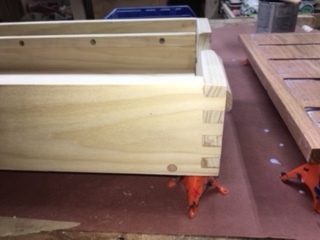
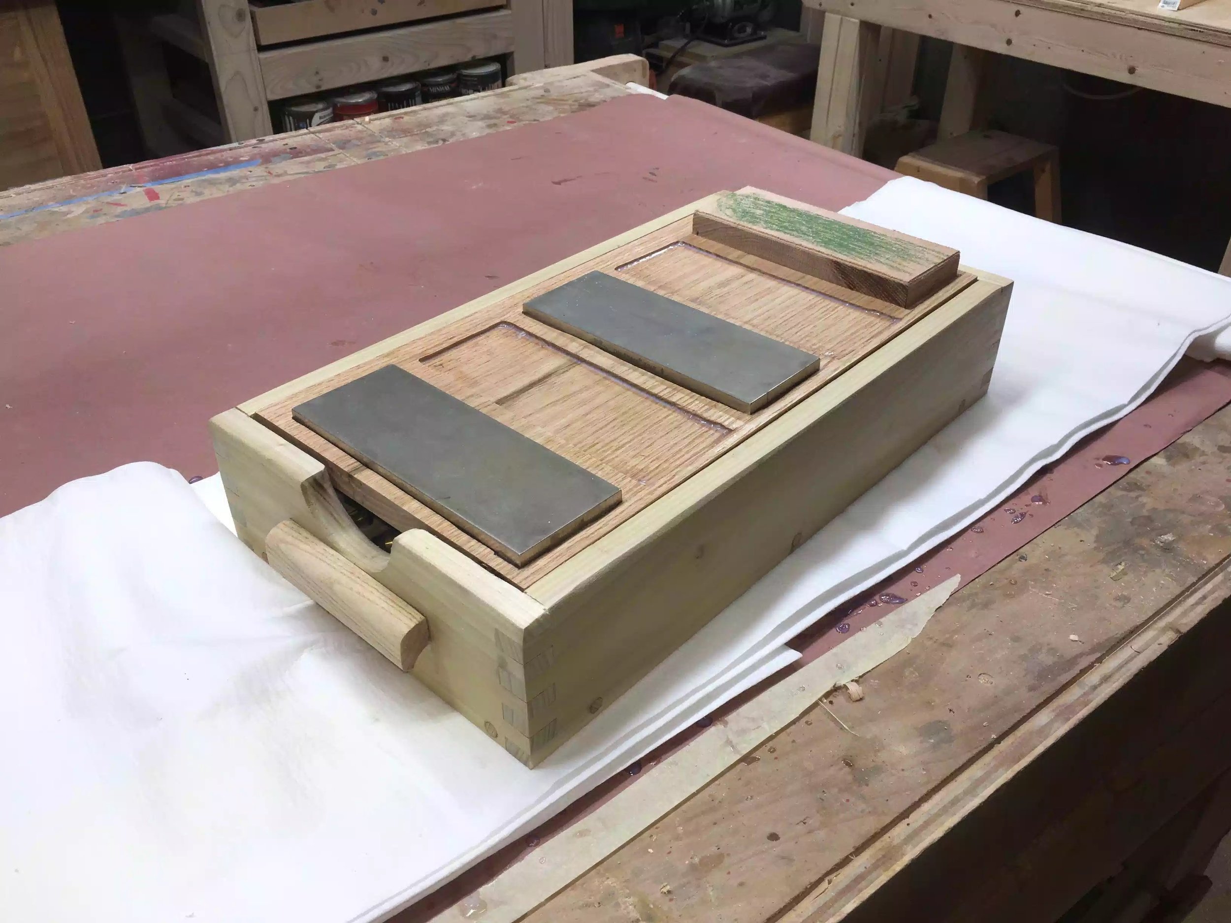
Here are a few pictures of the finished top, you can see the stones in place, I only have 2 diamond stones right now and I need to get at least one more, I will be putting a leather strop pad on the last recesss for finishing up my sharpening process, but that comes tomorrow.

Here are 2 stones sitting in the recesses , they fit great and will not be moving around.

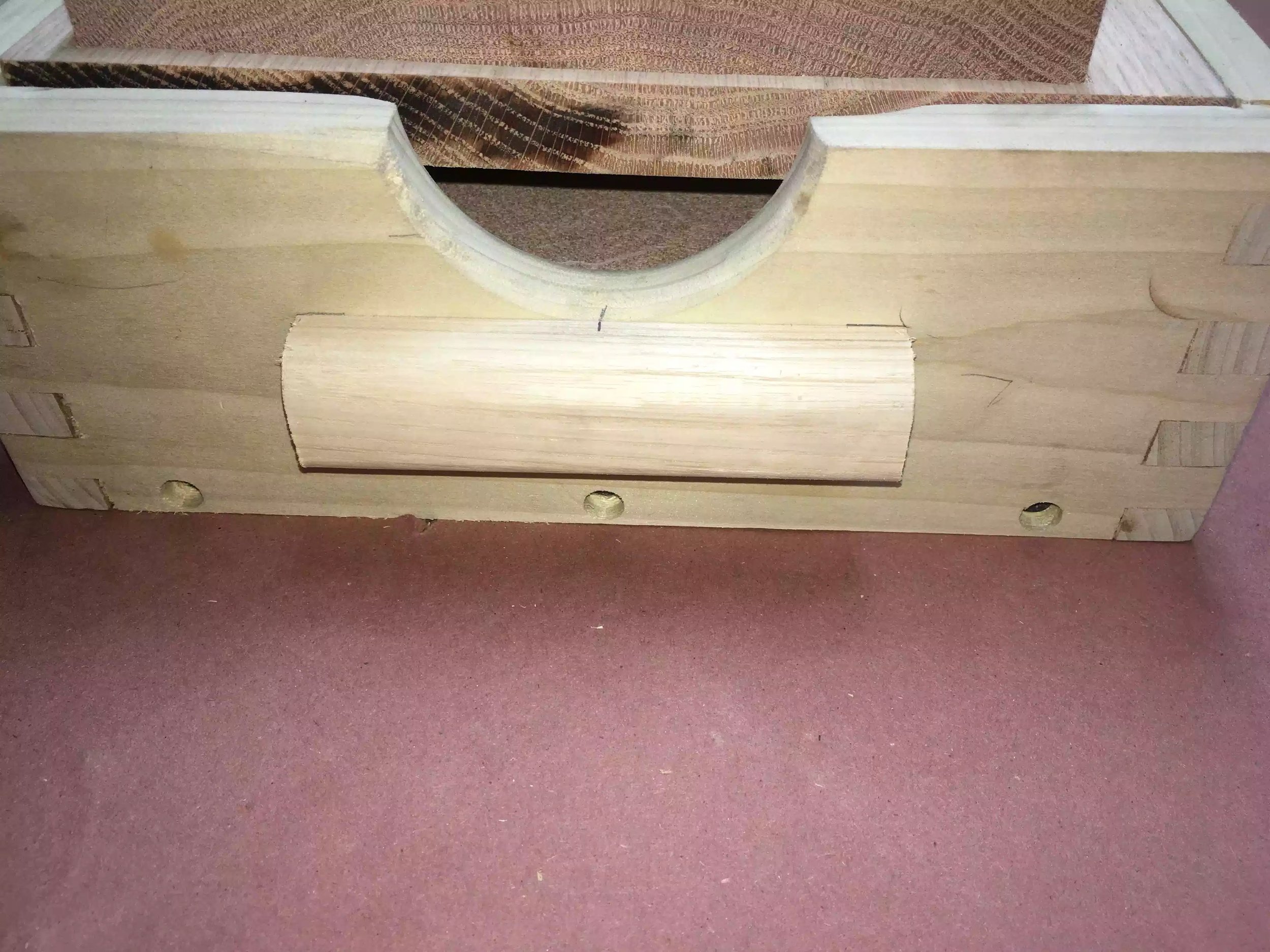
Here is the front of the sharpening station, I was thinking off adding finger pull holes to remove the sharpening stones but they are not so deep that I cant just lift them out of the recess.

Here is aside view, as you can see the finger holes are deep enough to pull out the top when I need to have access to the box contents.
Well that is all I had time for today,
Make a leather strop pad for the last recess, I have the leather, just need to figure out a way to add some thickness and rigidity to it.
Fill the screw holes with wooden plugs
Apply a finish to the station.
I returned to the project today after the weekend and I had the following steps to do.
Sand down the box frame after the glue-up
Make & Install the base
Cut the top to its final dimensions
Add some round-overs
The glue had set and I think I used a bit too much as the squeeze out was on the excessive side, so I took my random orbital sander and went through 120 - 220 grit sandpaper to clean it up. The finger joints look OK there was a few tiny spaces in between the fingers but I will need to fill them in later.
Anytime I get inconsistent spacing between joinery methods I usually use the saw dust and glue trick. All this is is the mixing of a little glue and sawdust from the same species of wood I use for a project in this case is poplar and rub it into the spacing let the glue set for about 30 minutes and then return to sand it down and magically the gaps disappear. I will do this towards the end of the project.

This picture shows the state of the piece after removing the clamps but before sanding it down.

Here is the box after sanding, need to fill in some little gaps around the finger joints but other than that it looks fine.
The base is nothing special , I am using a piece of 3/4” plywood as it will not be seen and then using the counter-sunk holes I already made around the bottom of the box parts I will use 1-1/4” screws to secure the base. I am not gluing it just in case I need to replace it in the future. I also needed to resolve a problem with keeping tools and accessories in position in the box an not be bumping into each other and possibly damaging them. To solve this issue I decided create a recess for the accessories I will be storing in the box, so I used my palm router and free handed the recesses to hold the tools. I will be using a similar process for the top but that is a much more precise recess and I will need to adapt the process whilst still using the router.

I used this scrap piece of 3/4” plywood for the base. I am cutting it down to final dimensions here on the table-saw.

I am layout out the lines so as that the honing guide sits inside and will not rattle around.

I used my palm router to remove the bulk of the recess and then went back with my chisel and mallet to clean up the edges.

Here is the honing guide accessories all nice and snug, Ill leave it for now and can always remove the base when I need to add more recesses for other tools. I still need to figure out how to store my sharpening stones in the box cavity when its not in use.

Another view of the base, before its secured to the frame.

Base is all secured and looks functional.
I am starting work on the top today but will need to finish it tomorrow. The top has a decent amount of work to do because it houses all my sharpening stones, I am creating recesses in the solid oak top so as that when I am using the sharpening station my stones stay stationary. To achieve this I need to use my plunge router together with a template that I need to make, I also need to use a template guide bushing on my router so as that I remove the precise amount of material for the stones to fit in, I purchased the Bosch bushing pack for my Bosch router which is the 1617 plunge router.
I will need to do a little more research on how to use a template for routing as I have never done it before. What I have so far I will show later.
As you can see from my 3D rendering of the project below the top is to receive 5 recessed sections for the stones and a stropping plate.

3D rendering of the sharpening station.
After researching online for a little while I found that I needed a couple of things before I could do this recess in the top. I needed to figure out the following:
Do I need tools that I don’t have for this task?
Do I need to make a jig of sorts?
Measurement considerations?
DO I NEED TOOLS?
After researching I found that I needed to buy a template bushing set for my router, a bushing is a router accessory that can be used with a jig, lettering, inlay work, even reproducing furniture parts. Here's the basic concept: A guide bushing mounts to the router's sub-base with a tube that protrudes below. A straight router bit extends through the tube. The outer surface of the tube rides against an edge guide or template, keeping the bit a set distance (offset) from the edge guide or template, see picture below.

Here is a picture that I found online to show the bushing in the router.
In the marketplace you'll find two bushing styles. The Porter-Cable two-piece (shown below) uses a screw-on locking ring to hold the tube part to the router base. This style fits a wide range of models. The other style of guide bushing clicks into place, but only fits Bosch routers. If your router doesn't accept these common styles of guide bushings, consider buying adapters and sub-bases .
The style of bushing I needed was the one pictured on the right below.

DO I NEED TO MAKE A JIG?
I don’t necessarily need a jig of sorts but I do need to make a template. A template is guide that I will use in conjunction with the guide bushing so as to guide the router to the shape that I need to create. I have decided to make the template because I have quite a lot of milling to do as I need to create 5 recesses and to do that free hand would be extremely difficult and would also mean a lot of clean-up when I was done with the router. Using a template negates all that clean-up probably with a chisel and also provides nice clean edges in less time.
I need to figure out how to make the template, that is tomorrow!!

Here is my router and bushing set.
To figure the offset, measure the outside diameter (OD) of the guide bushing tube and subtract the diameter of the bit. Next, divide this figure by 2 to determine the offset. In the example at below subtract the 1⁄2 " bit diameter from the bushing's 3⁄4 " OD. You get 1⁄4 ". Now divide this number by two and you arrive at a 1⁄8 " offset.

This diagram can aid in how to calculate the offset
This where I leave it for today, I had the main box, bottom and top made. Below are some pictures as to where I left off today.

The lid is on but that about it, I need to put the recess in tomorrow.

The finger cut out fits perfectly for my fingers to fit in and pull off the top
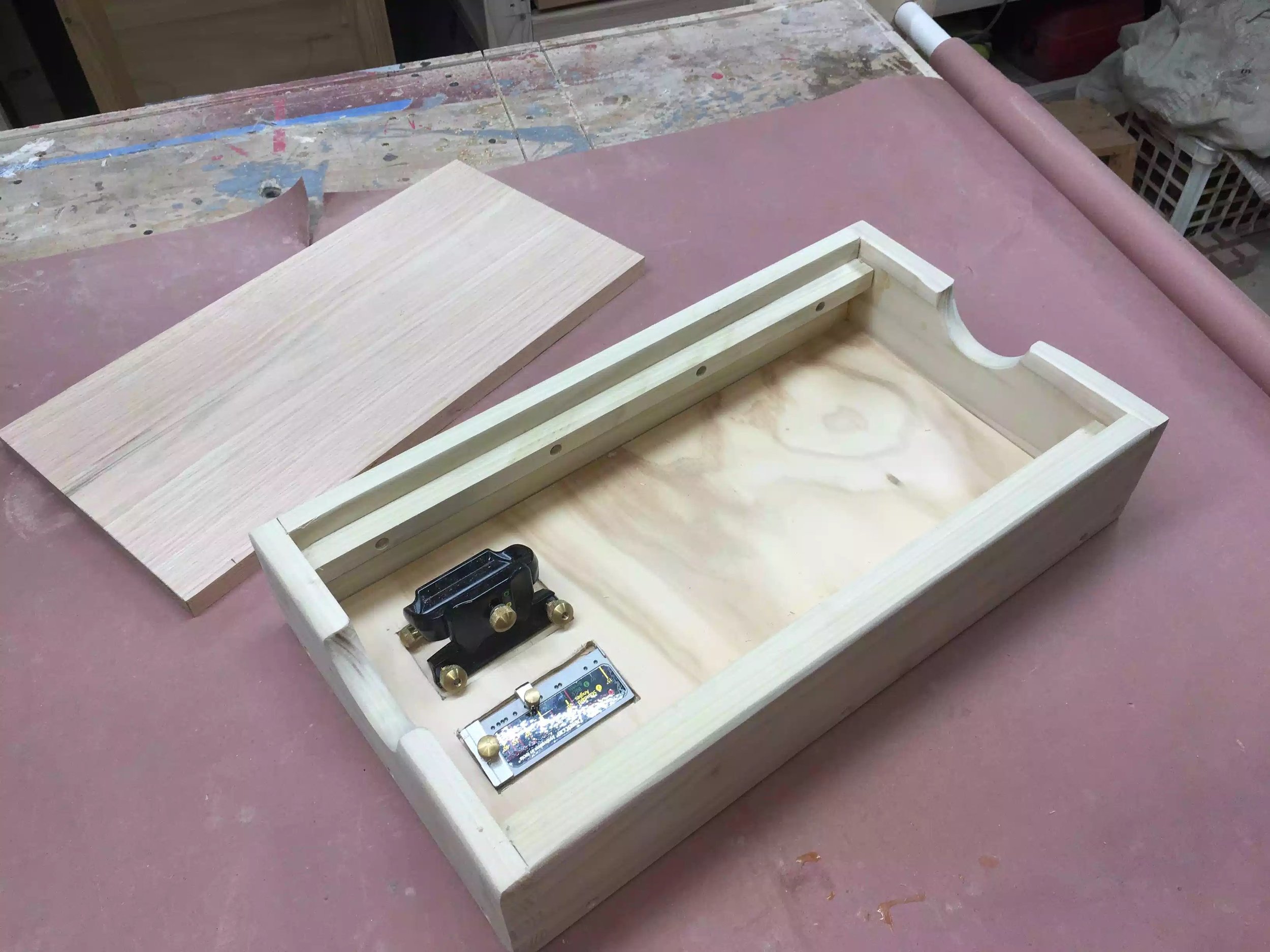
Some accessories in there nice new recessed homes.
Make template for routing the recesses
Make side handles
Apply finish, I usually use a poly-crylic for shop projects.
Start sharpening
Until the next day, take care
Ed


