Some times its beneficial to make a prototype of the project that you eventually want to make especially when you are marrying 2 elements together, most of the time on a project this size its not always necessary but I had to many unknown measurements especially considering putting glasses in the flight, and also it helps to have a tangible object in your hand to see any design elements that might look great on a computer but look bad on a finished project.
Below are the steps I took to make the prototype:
I used plywood to make the prototype as I had some on hand, but really any material could be used to make it. So my first step was to cut 3 pieces of plywood to my dimensions for the beer flight, a top and 2 sides
Next I had to do some layout
Cutting the circles & Circle cutting tools
Cutting the dadoes
Router Work
A little assembly
THE PARTS
There are only 3 parts to the beer flight, the top and two sides. Below is a picture of the plywood parts, when I actually get to making the flight I will be using 3 species of wood that I will need to glue up but I don’t have to do that now and this prototype project only took me like 90 minutes to make.
Here are the parts, the back pieces are the sides and the front piece is the top of the flight.
SOME LAYOUT
There was quite a lot of layout work in the design phase of this project, so I took all my dimensions from Sketchup and that was one of the main reasons I am making this prototype. Here are some of the dimensions that I needed to layout
Centering the holes for the glasses on the flight top, making sure to keep clear of the left & right legs that were underneath the top. So I measured 2-3/4” from each of the sides (left & right), the second measurement was 5-1/4” repeat that measurement as i did on the first. I also need to draw a centering line 2-1/4” from the top edge and where these lines intersected was the center hole I would use my hole saw to drill out the piece (more on that later)
Next for determining the center hole for each of the 4 holes that will be cut for the glasses. I needed a 2” diameter for each hole and I also wanted a 1/2” space between each of them holes. This was another reason for the prototype because I wanted to make sure that the 1/2” space was enough so as that the glasses didn’t bump into each other as the style of glass I was using had wider top than bottom.
Next piece of layout was for the feet mainly because I was cutting 3 half-circles into each piece. A half circle was to be cut halfway up the left & right side of each foot and that hole diameter was 1” and one half circle on the bottom and that diameter was 2-1/2” wide centered on the foot.
Here is the layout done on one of the feet.
Here is he layout on the top piece, I also drilled pilot holes for the hole saw to track correctly.
Here is the layout for the dadoes, I measured 1/2” from each side and drew lines indicating where I wanted the dado to go, that’s later.
CUTTING THE CIRCLES & CIRCLE CUTTING TOOLS
So since all of my layout lines are in place I needed to actually cut the circles that I incorporated into the design. I used three different diameter hole saws (1”, 2” & 2-1/2”)for this and I also used my bench-top drill press doing this, you could use a handheld drill but it would be difficult especially on the half-circles.
I used my Milwaukee Hole saw set as it had all the circle saw diameters that I needed, what a great tool even in a under-powered drill press like mine.
Here is a close-up of the 2” diameter hole saw.
Here is my current drill press set up, if you would like more information on how I made the drill press table or drawer cabinet you can find more information here.
Cutting the circles started with me cutting the 2” diameter holes in the top, I needed to cut 4 of these as they will house 4 glasses.
Here is the work-piece positioned under the hole saw, the work-piece was turned end for end to get both left and right sides done, the saw did a great job as I didn’t get any burn marks on the work piece.
Here is a close-up of the circle cut-out.
Next I needed to cut out all the half-circles in the feet and I needed a method that would not waste any of the wood I have, So I came up with a method on the drill press that allowed me to cut the feet to exact dimensions not bigger, sure I could of made an overside work-piece and drill the full circle out and cut the circle in half but that meant wasting wood.
So the method I came up with was to use 2 sacrificial plywood scraps to go either side of the the work-piece which were stuck in place with double sided tape on my drill press table and support the entire cutting edge of the hole saw and when I was finished I could put another work-piece in place and repeat until my sides were milled.
also another thing to note that the feet had 2 different diameter half-circles to be cut if you remember from my layout.
Below are some pictures of the process.
Here is one of the sides in place and to the left and right are 2 sacrificial pieces, he idea was to make sure that the entire cutting surface of the hole saw had something to drill into , thus keeping the hole saw tracking in the downward direction and not chewing up the main piece, and it worked out great. This picture shows me drill the 1” diameter holes on the sides of the feet.
Here is another shot showing all the holes drilled out.
Here is a close up of one of the sides. Came out great
CUTTING THE DADOES
The joinery method I will be using to join the feet to the underside of the top will be dadoes. These are just grooves that I cut out at the table-saw with my dado stack, the width of the dado stack is determined by what thickness wood you are using. I measured 1/2” from the left and right side.
The other main reason I was doing a prototype was because I wanted to make sure that when the glasses were sitting in the flight that they didn’t interfere with the feet in any way, and thank god I didn’t.
Here is the bottom face of top and you can see the 3/4” wide dado that is also 1/4” deep into the top.
ROUTER TIME
Finally I wanted to add some decorative elements to the flight so I used my router with a 1/4” round-over bit in the router to clean up all the rough and sharp edges left on the outside edges of the parts, I also wanted to add a round-over to the inside edges of the holes where the glasses will be sitting.
One thing that I might change is using either a different router profile bit for the edges on the top, or just using a 1/2” round-over, but I need to think some more on that.
Below are some pictures of the round-overs that were applied.
Here is the round-over profile added to one of the holes on the top. This will look a lot better when its actually wood.
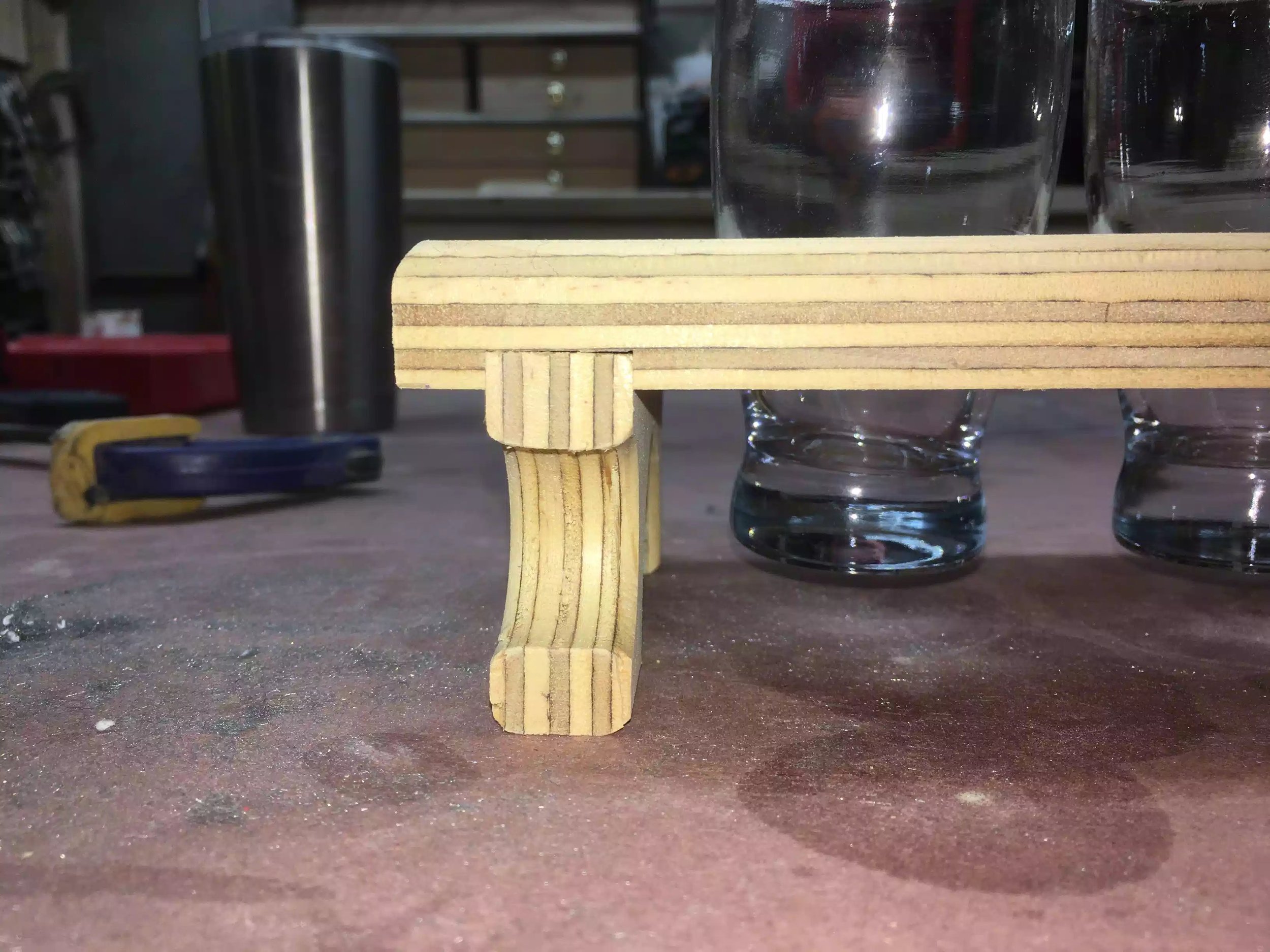
Here is one of the feet rounded over. I like the look of it and don’t think I need a larger bit.
Here you can slightly see the round-over to the top, its very faint that is why I am thinking of using a larger round-over bit , or perhaps even a roman ogee profile might look better, food for thought.
ASSEMBLED PROTOTYPE
I am so glad that I made this prototype and got most of my questions answered and happy to realize that all of my dimensions were correct, although it will take a decent amount of time in fabricating the feet I think they are worth it and really think they will look great in the woods that I will be using.
I also like how the transition from the feet into the top is really nice and love the look of the very visible dado that will attach the feet to the flight. The only thing that I am questioning is the width of the flight top which is 4-1/2” wide, thinking possible that is too wide for 2” diameter glasses, so maybe after-all I will be adding a larger round-over profile to the top which will eat away some of that 1” on the front and back edges of the flight.
Below are several pictures of the finished prototype, I hope you like.
Frontal picture showing the glasses in there homes, there is about 1” clearance from the glasses to the table-top. Love the dado joint.
Here is the top view, 1/2” gap is perfect.
Here is the side foot, I think this is my favorite aspect of the prototype, really like the curves.
Even in plywood the dado joint looks awesome , imagine what this will be like in the real deal.
NEXT:
I will be starting the build. Hopefully I will catch you guys later.


