WINDOW BOX'S: ALL FINISHED

Well this weekend finally saw me complete all 3 window boxes. I made 2 different sizes and used 2 different wood types let me go into a little more detail about them.

CEDAR WINDOW BOX

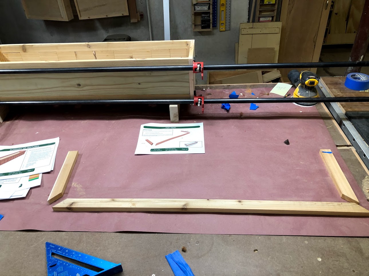
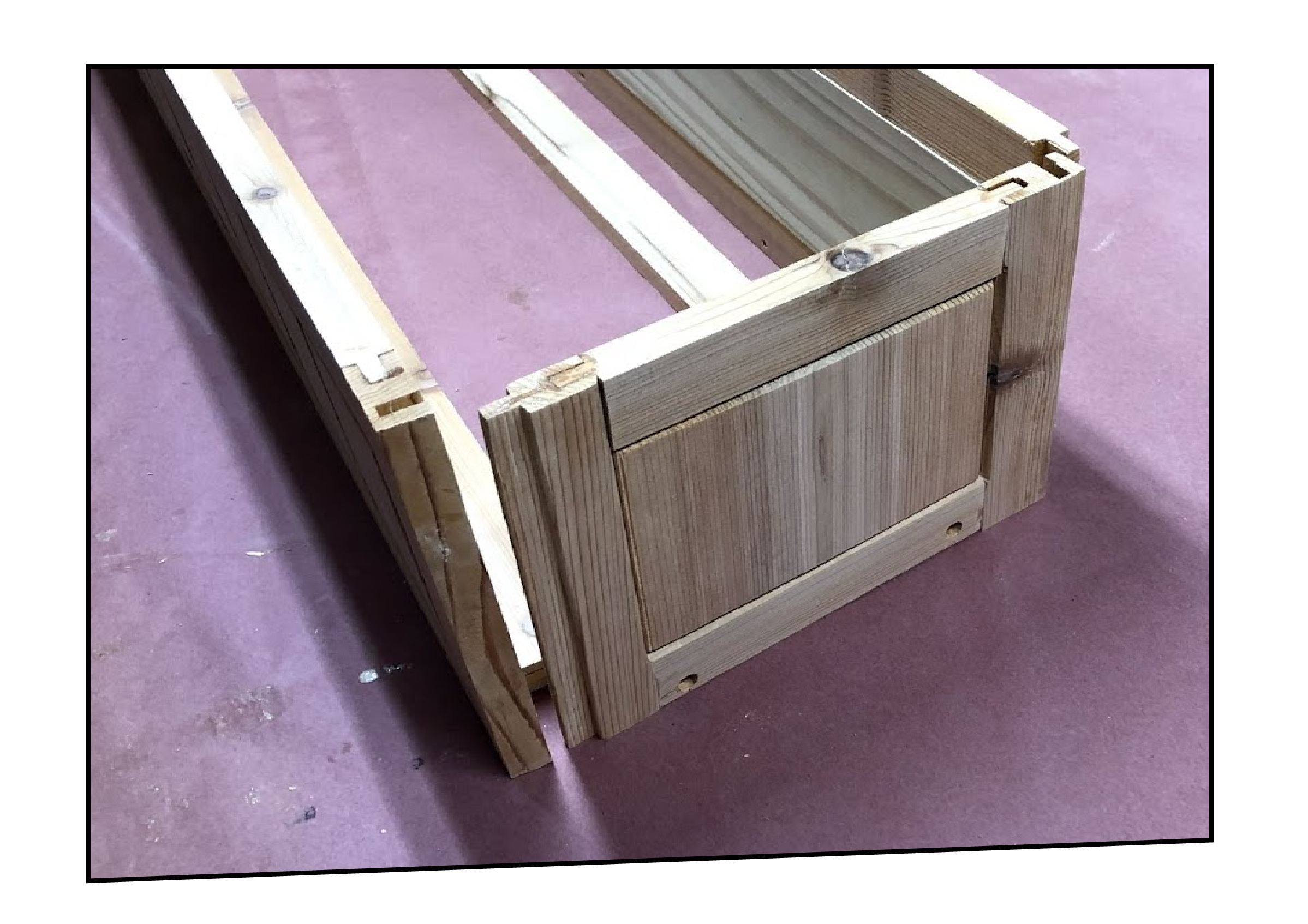
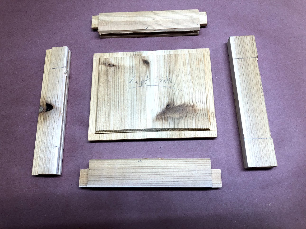
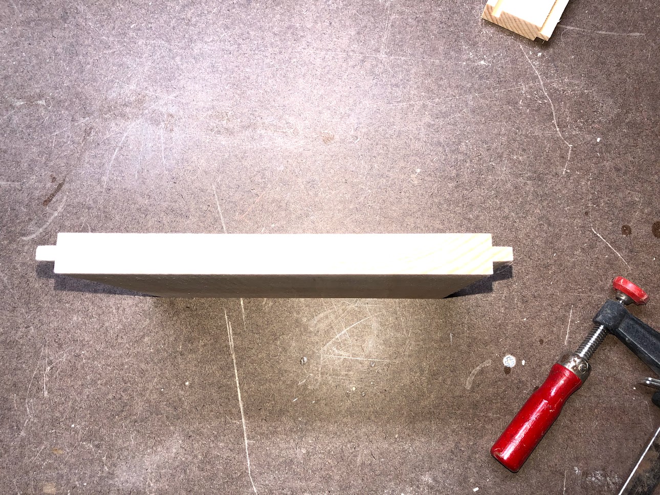
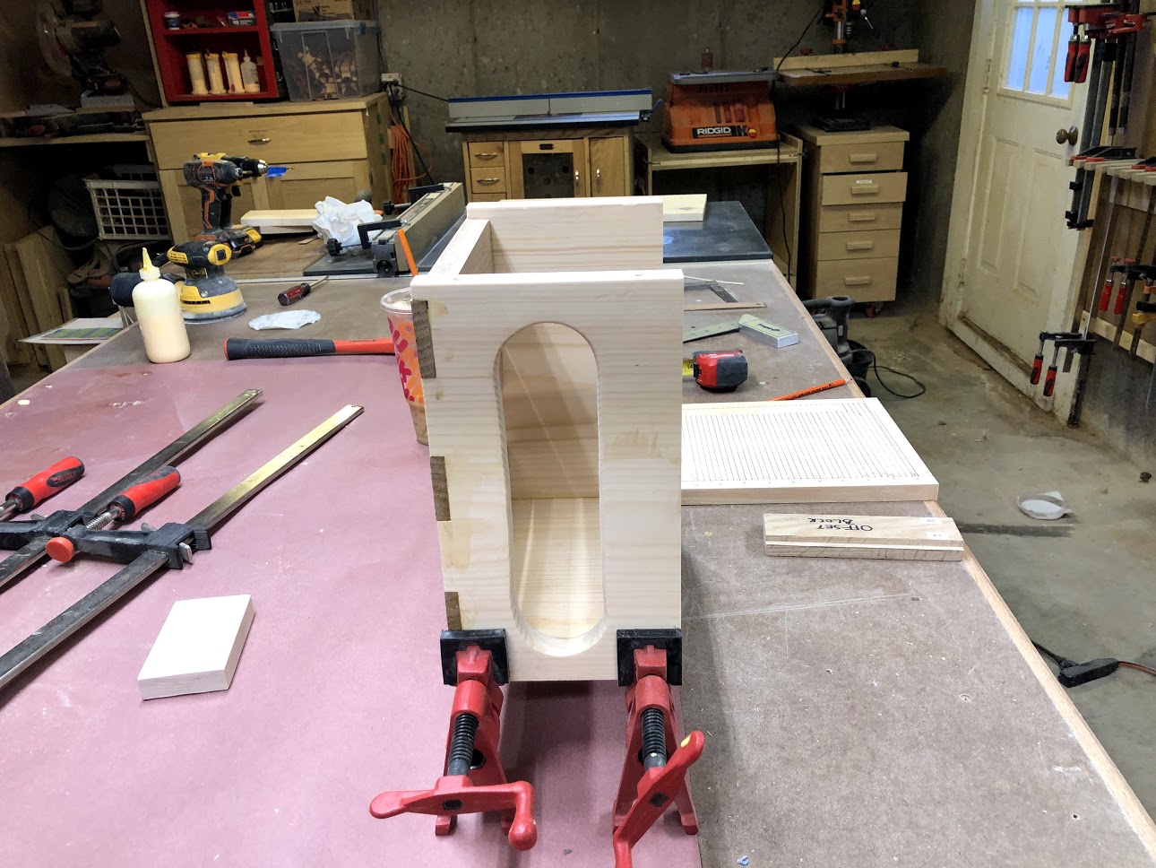
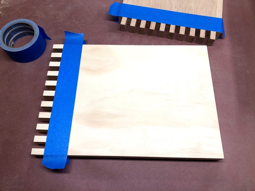
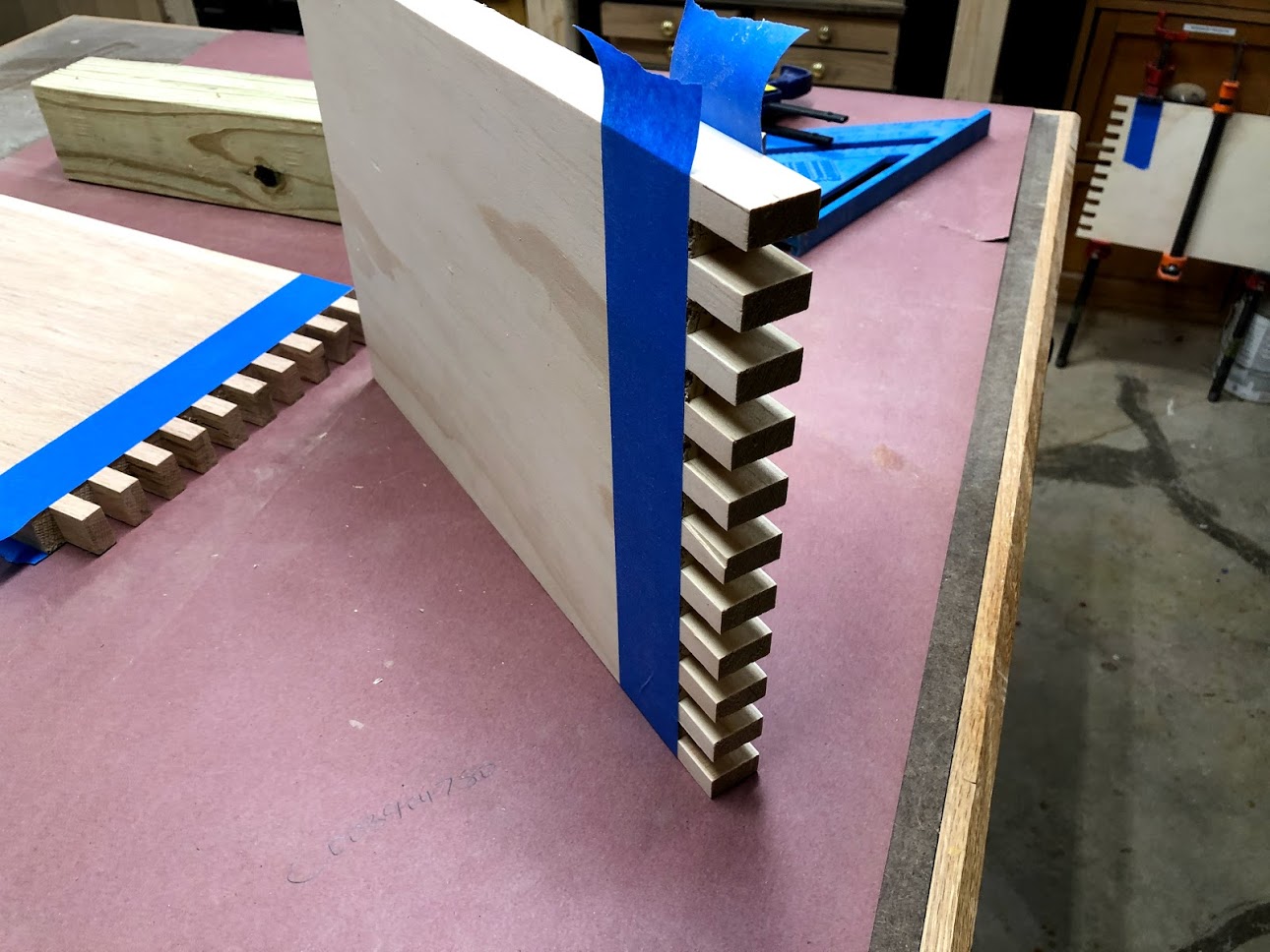
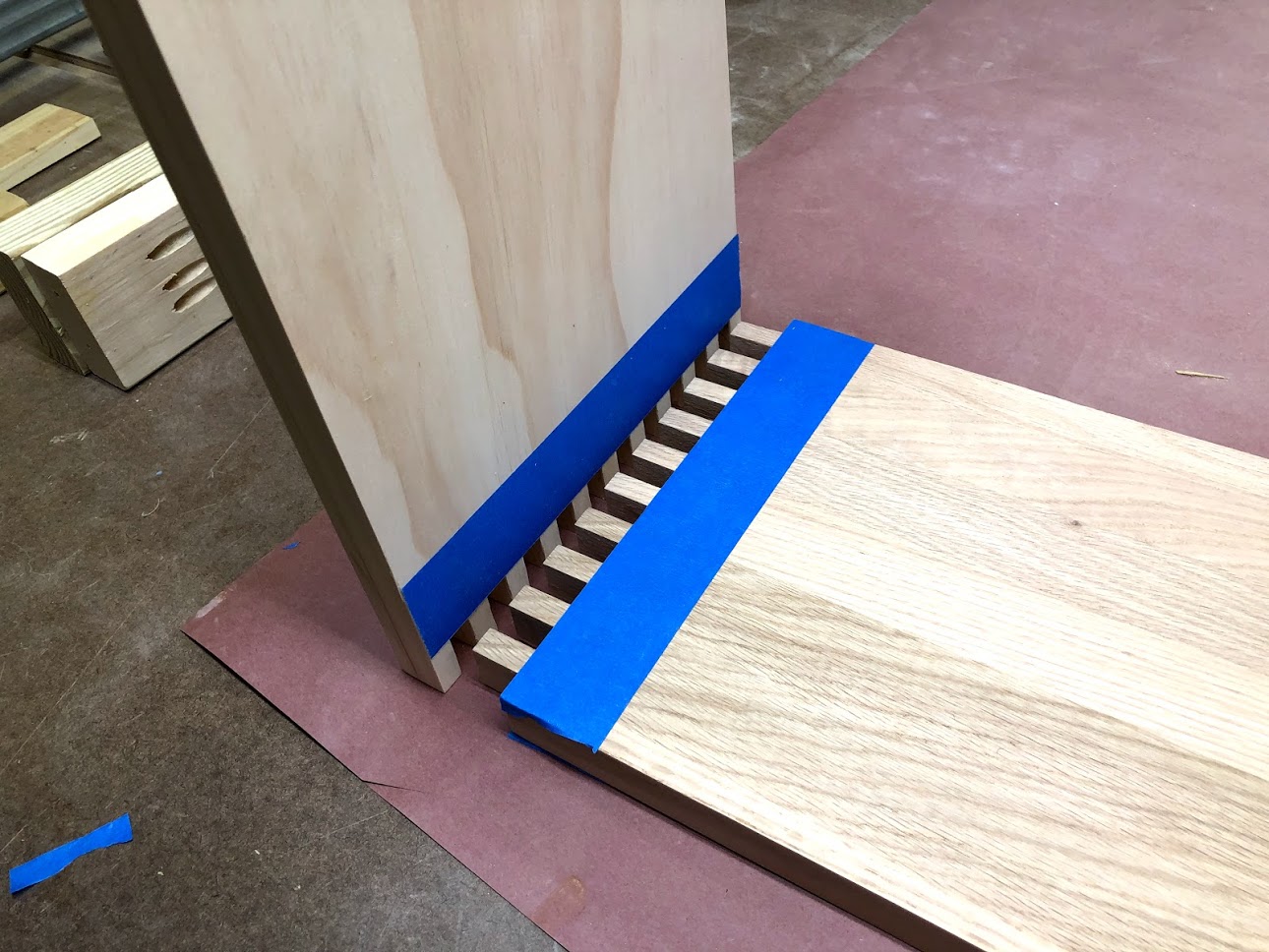
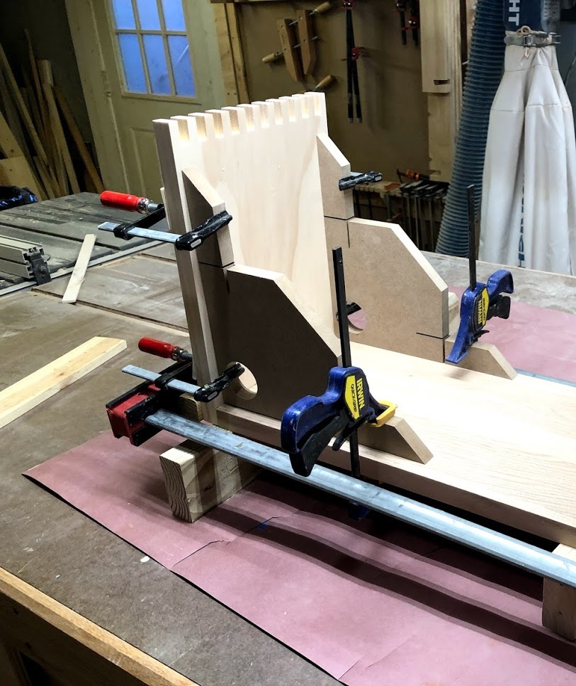
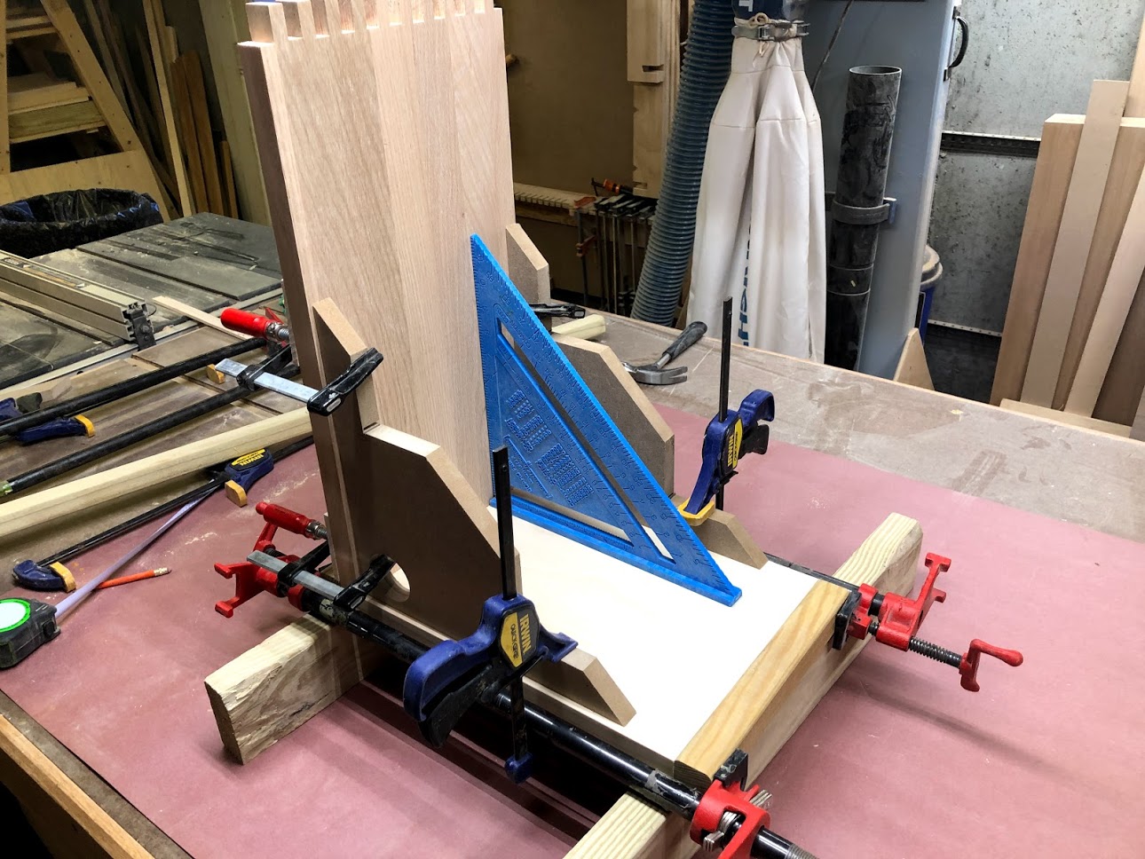
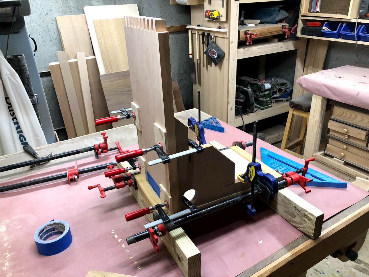
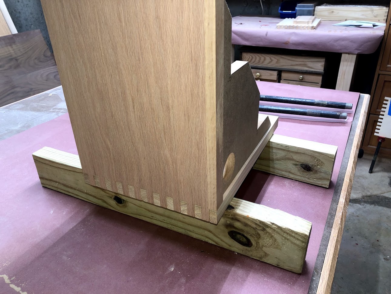
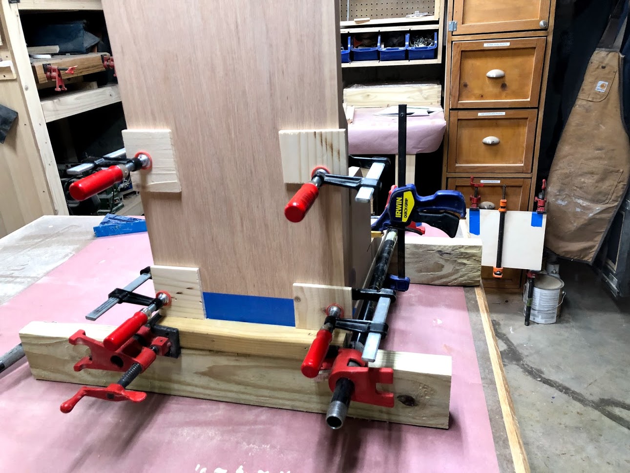
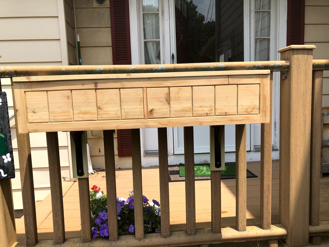
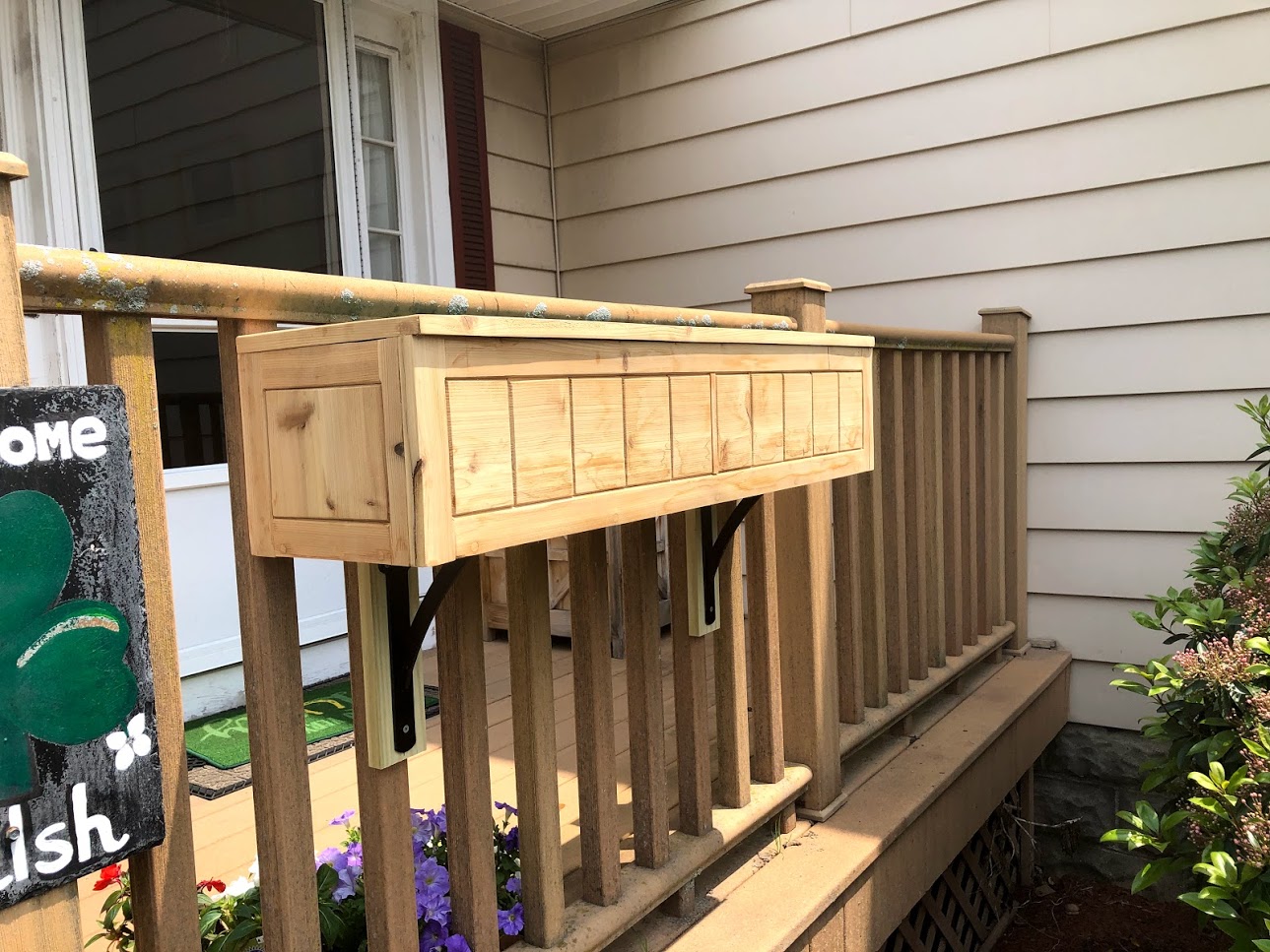
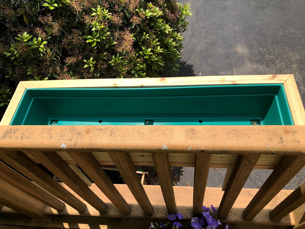
The first window box that I made I used cedar wood to make it, I used frame and panel construction techniques to make it. It is also the largest of the 2 sizes of box that I made at 40'‘ basically because I had to purchase a long cedar board so I decided to use the entire board and have no scrap left over.

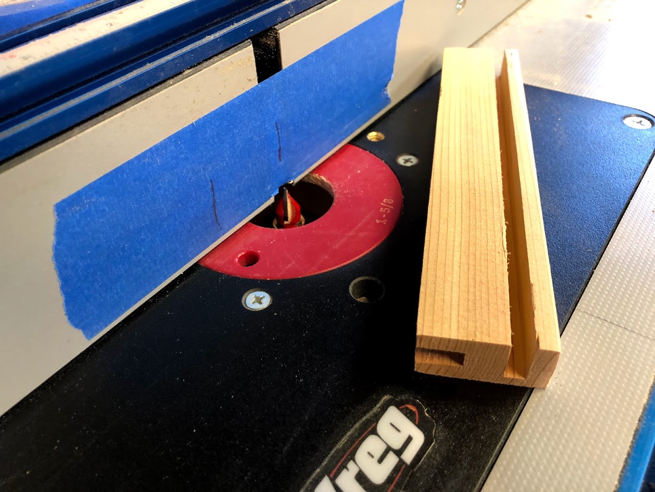
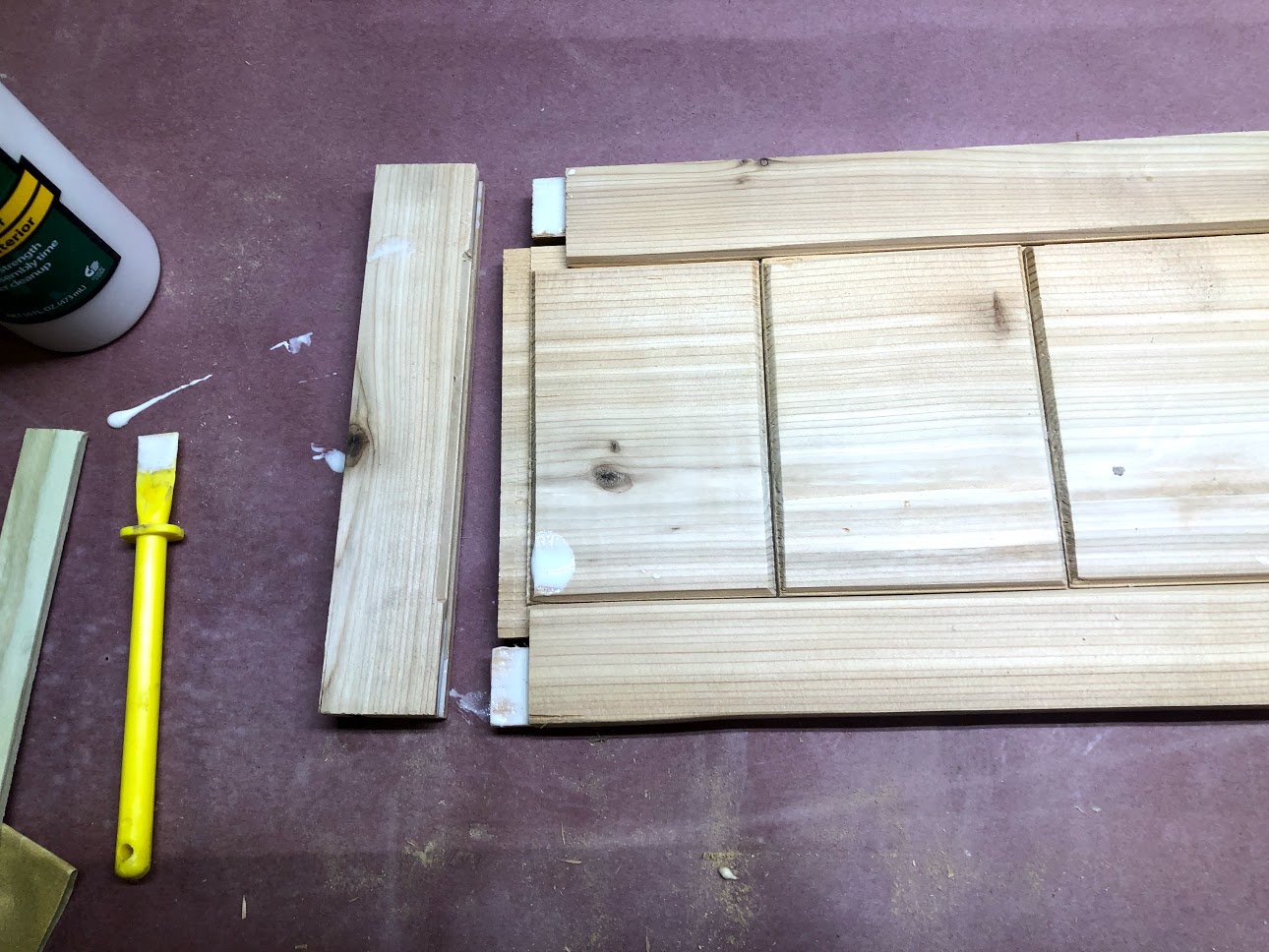
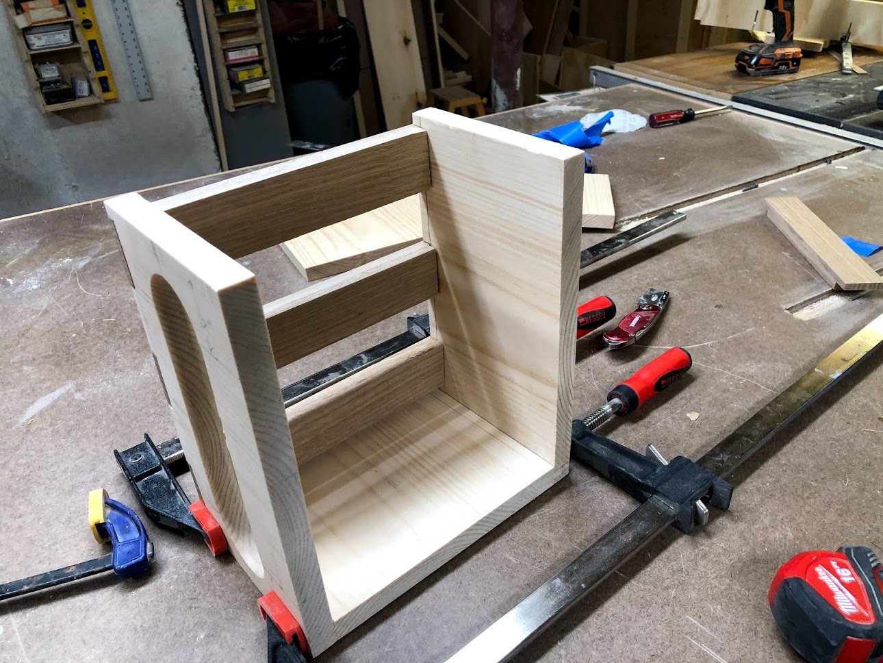
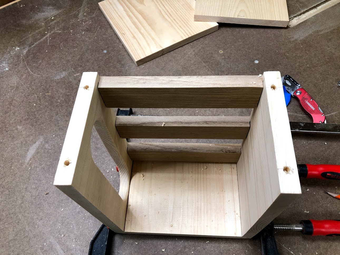
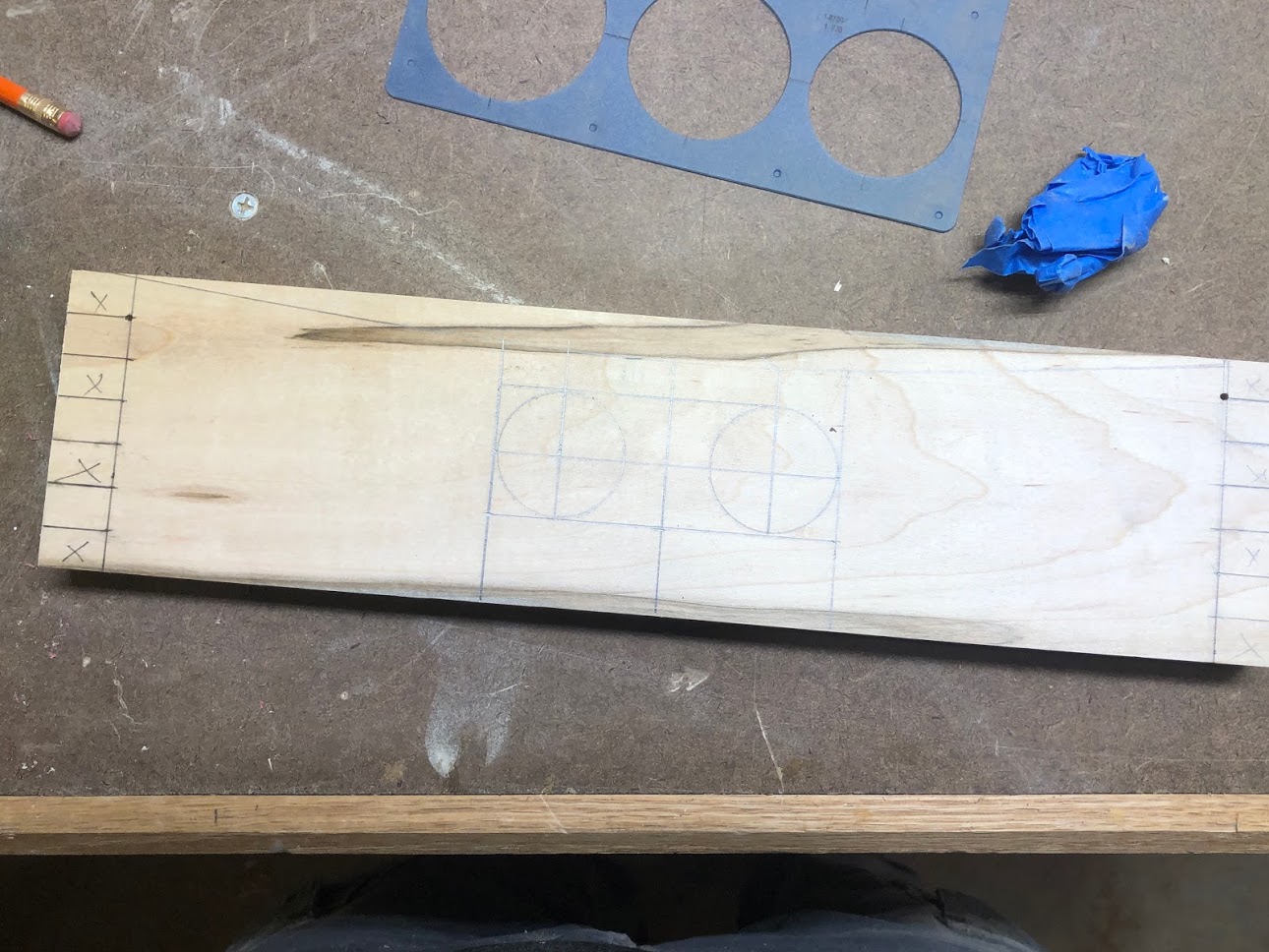
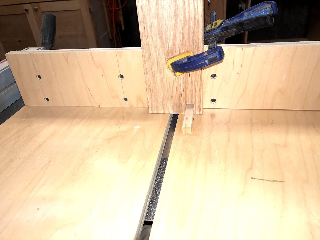
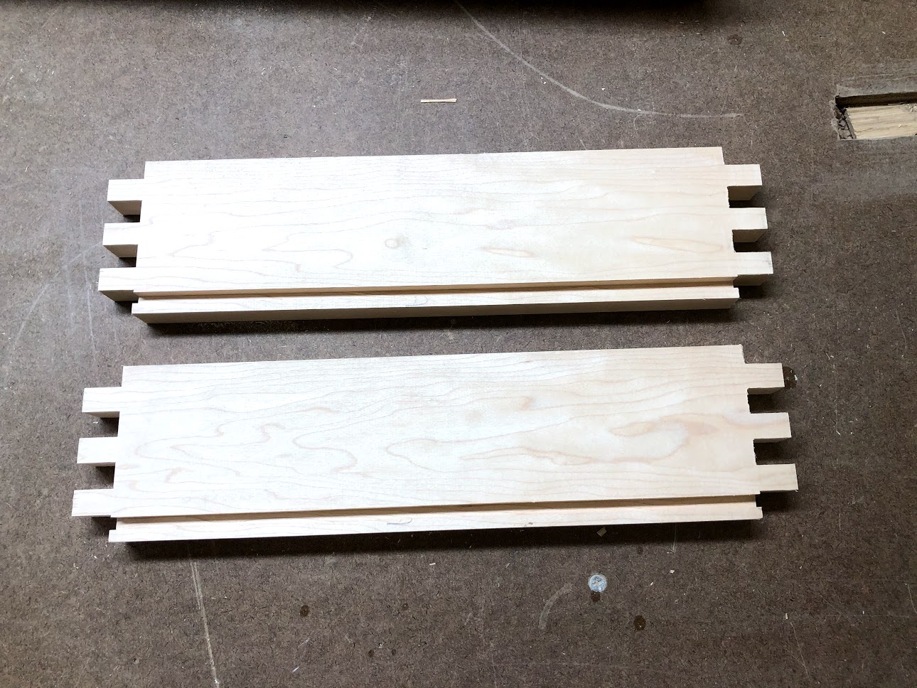
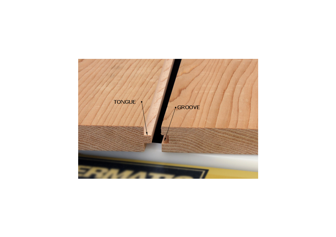
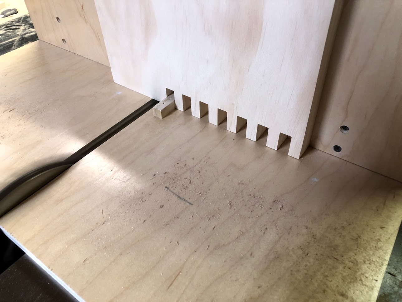
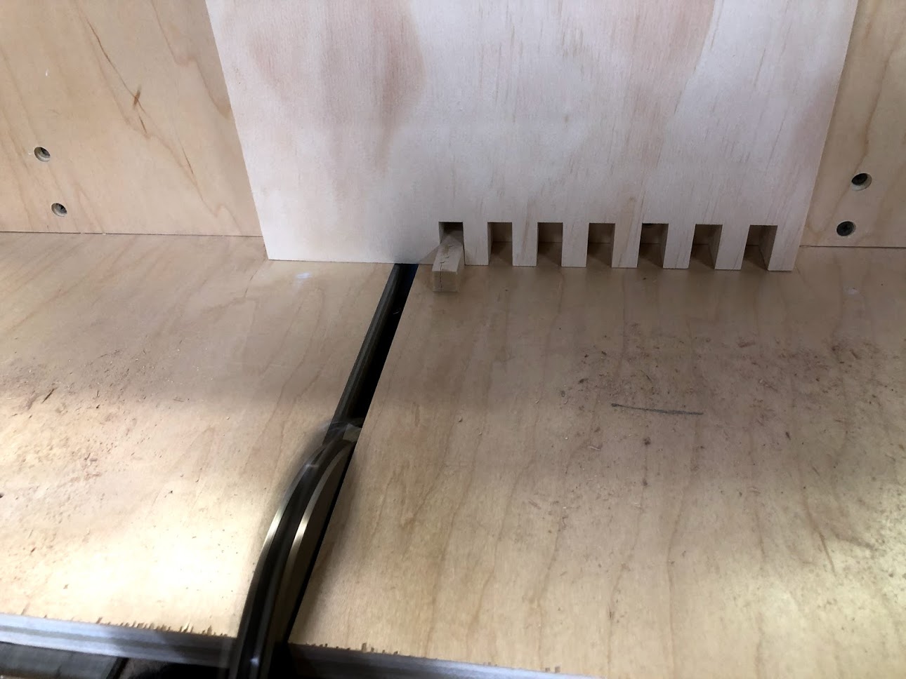
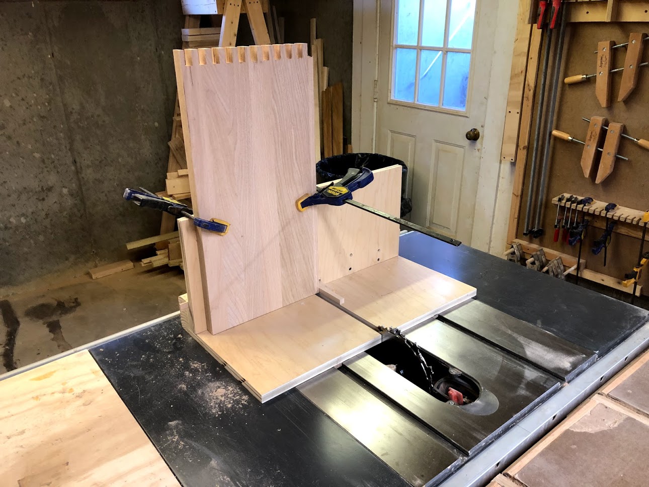
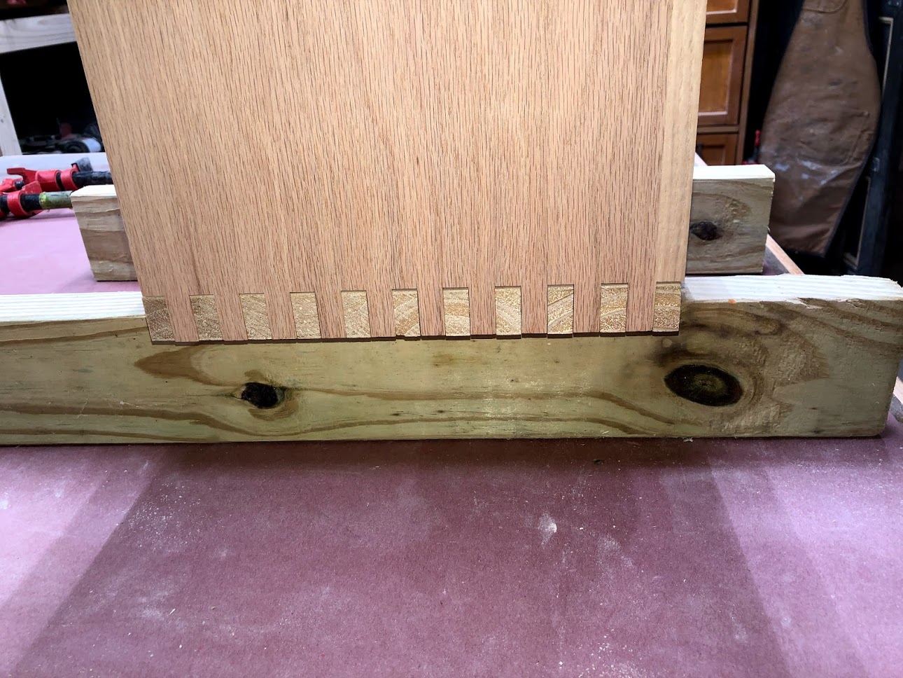
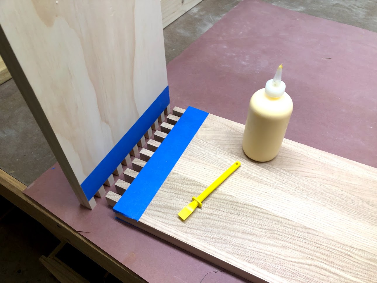
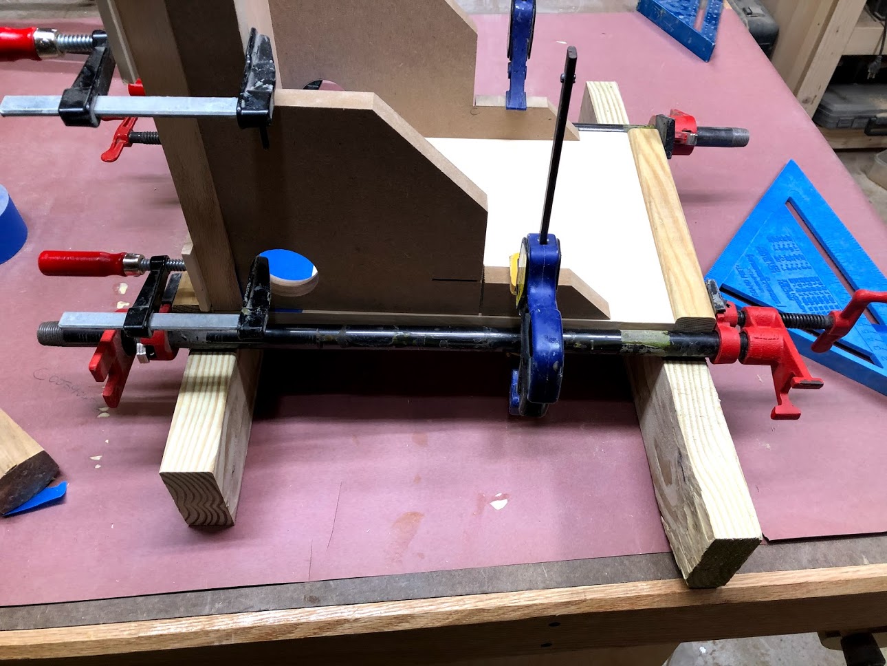
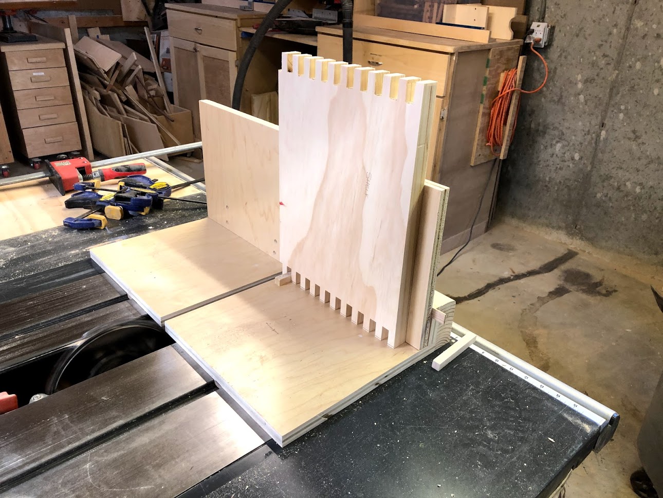
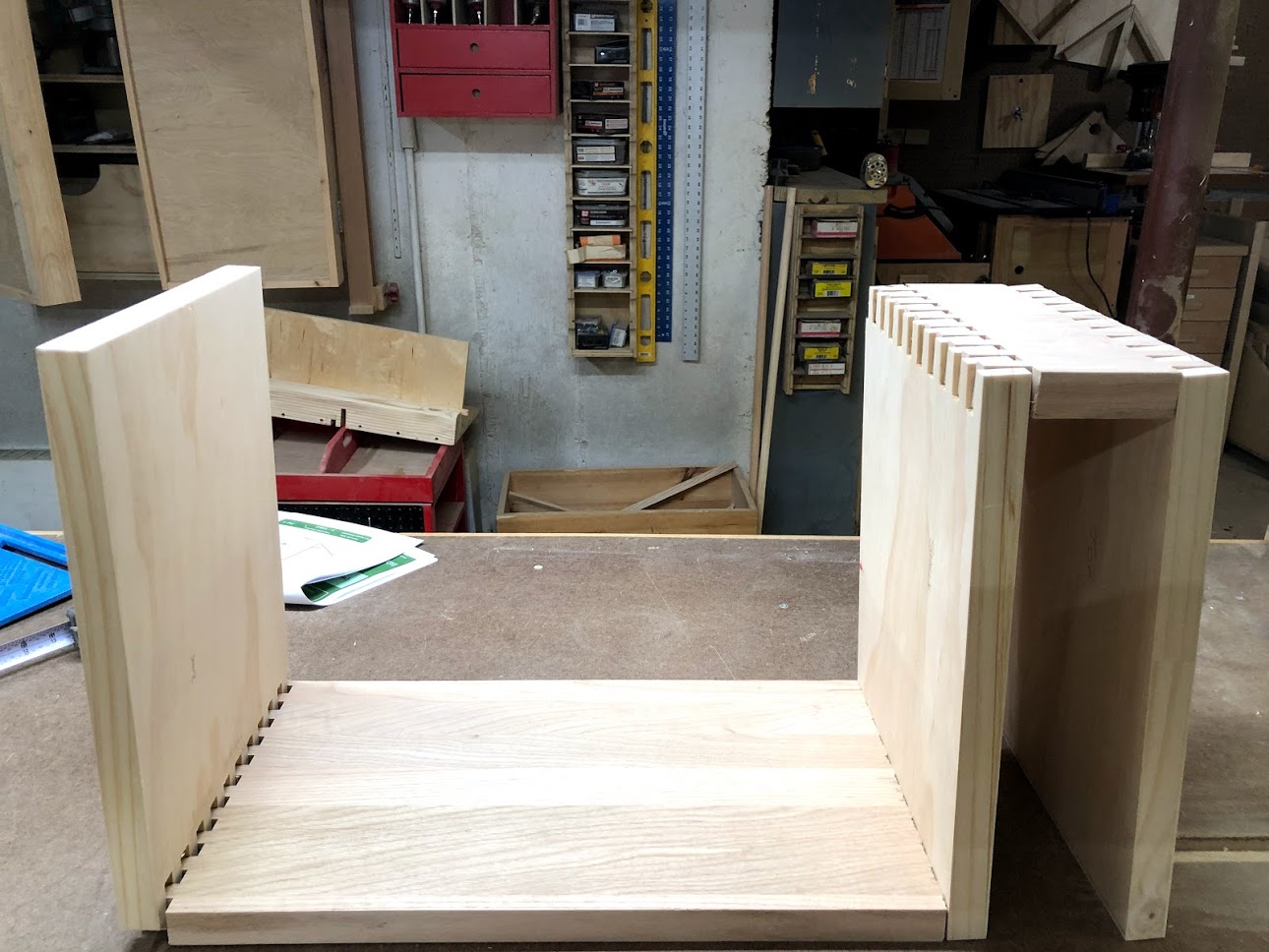
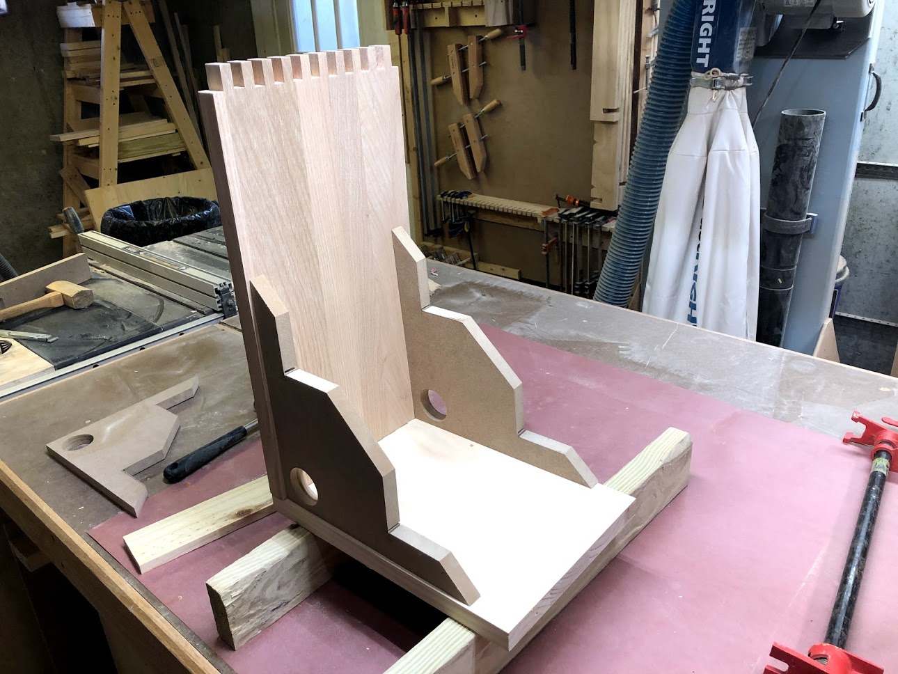
The joinery I used was traditional tongue and groove with inlaid panels on the front and sides of the box. I used frame and panel construction because it allowed me to incorporate more design features into the aesthetics of the window box. I was able add grooves to the panels that made up the front and sides to further enhance the look of the box and not just have solid wood panels beside each other and to be hones I really like the look of the window box and its very pleasing to the eye.

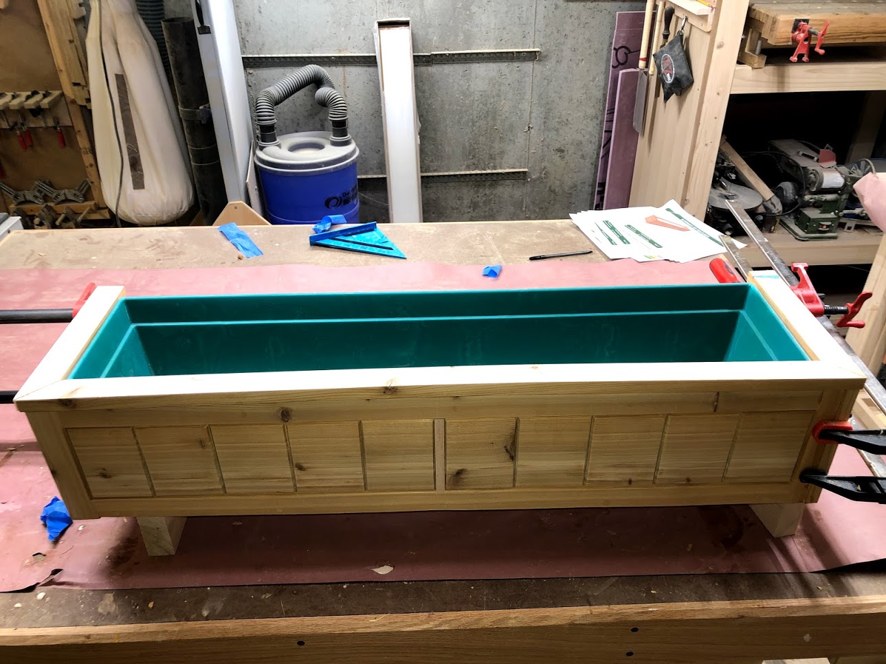
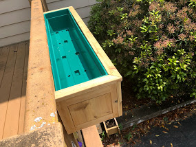
I also used plastic liners to go into the box so as that I could remove the it in order to put plants into the them then just place it back into its home.

To mount the window boxes I purchased some black Roth iron L brackets and secured them to the balusters on the front porch. and then just screwed the planter onto them.

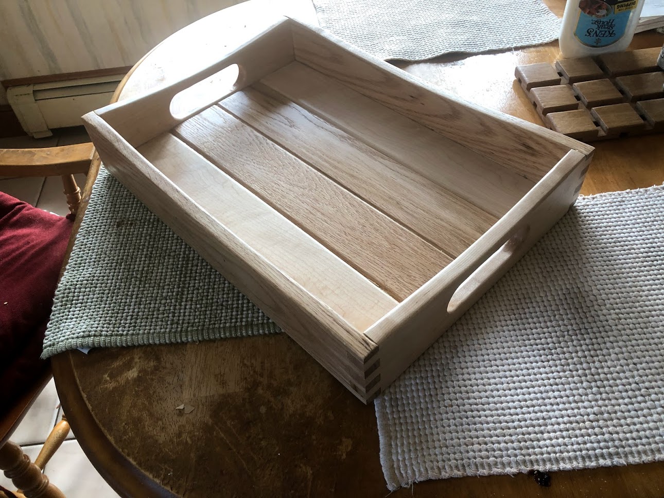
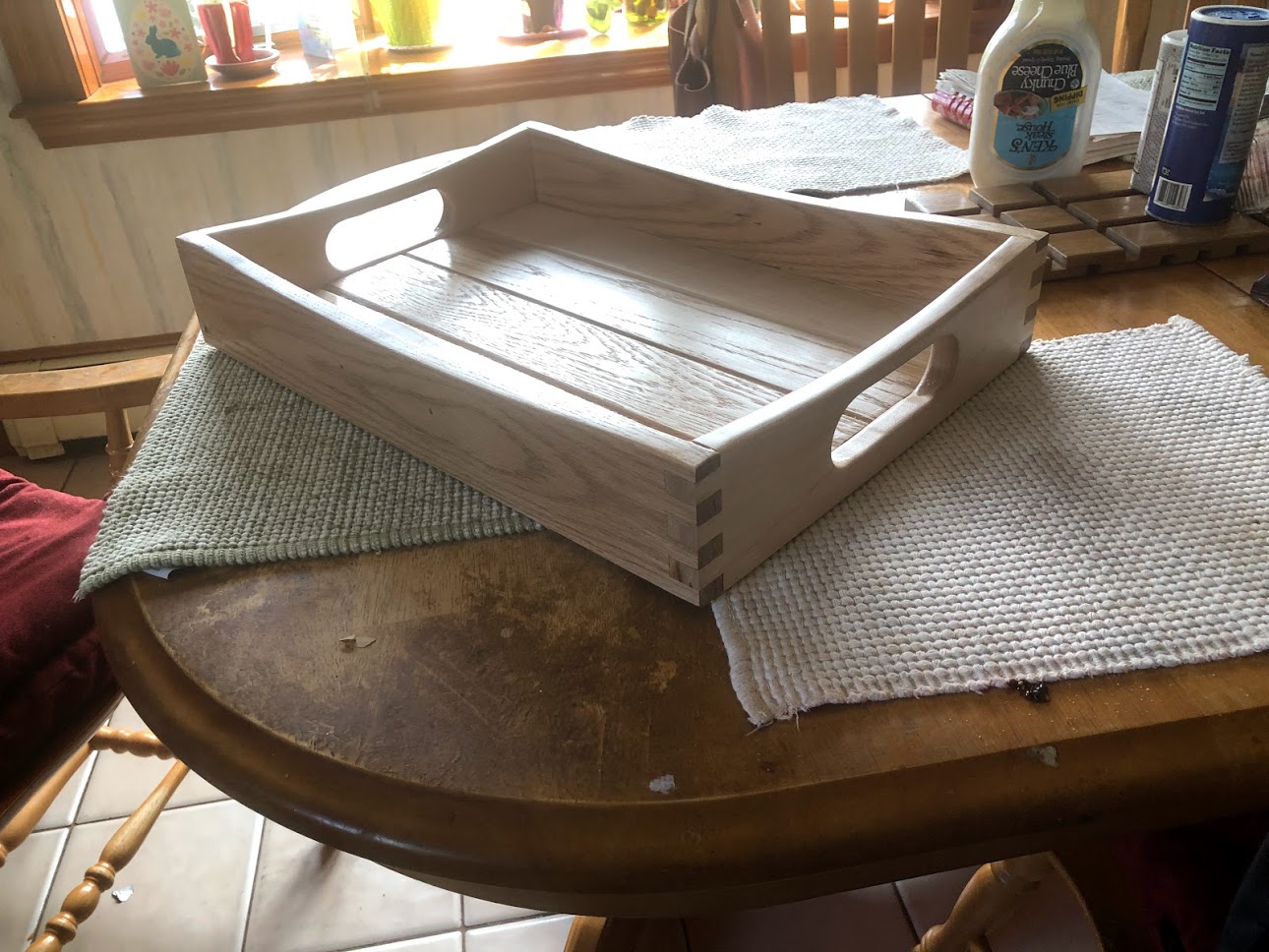
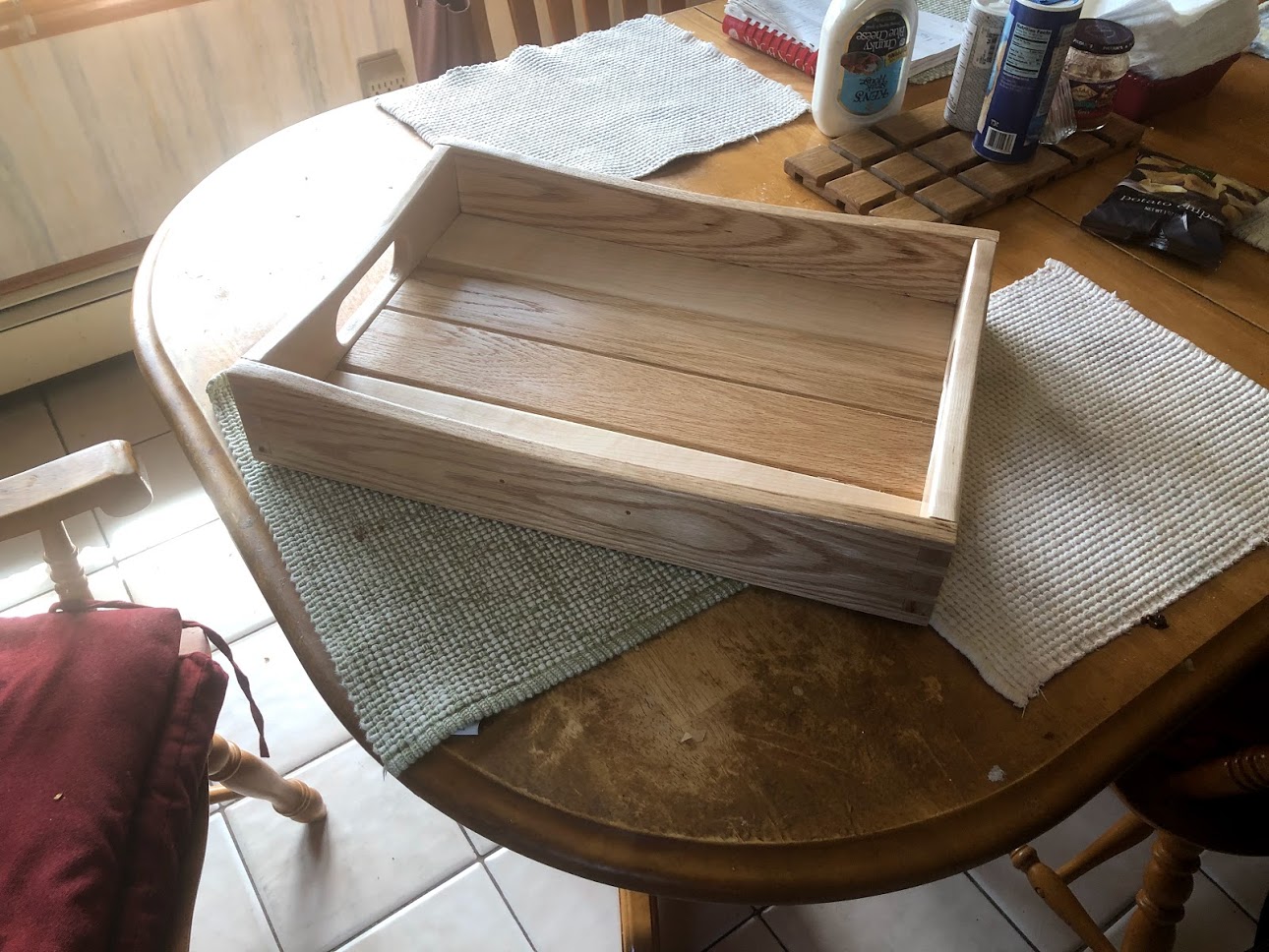
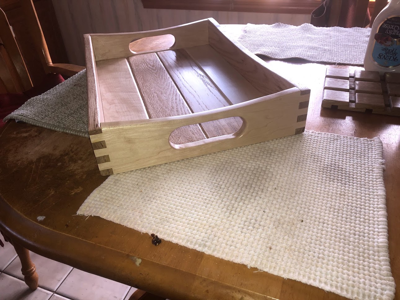
Below is a compilation of pictures with the finished window box. Also I did make an entire set of plans for both size boxes and I will post them soon I just need to tweak a few things to make them ready.

PRESSURE TREATED WINDOW BOX

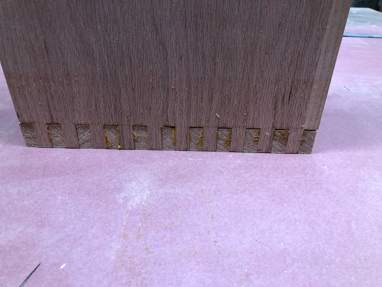
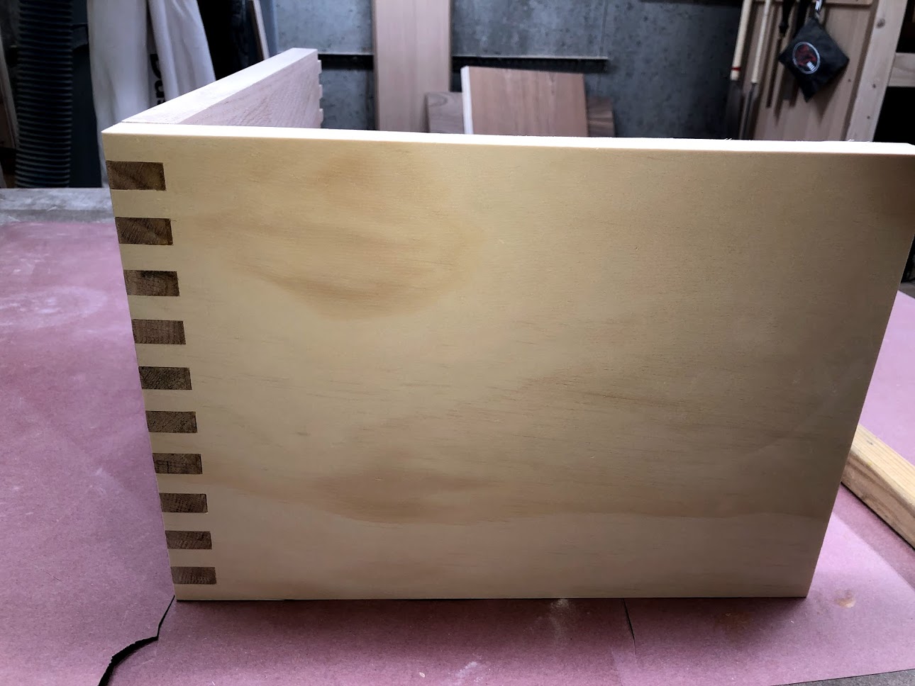
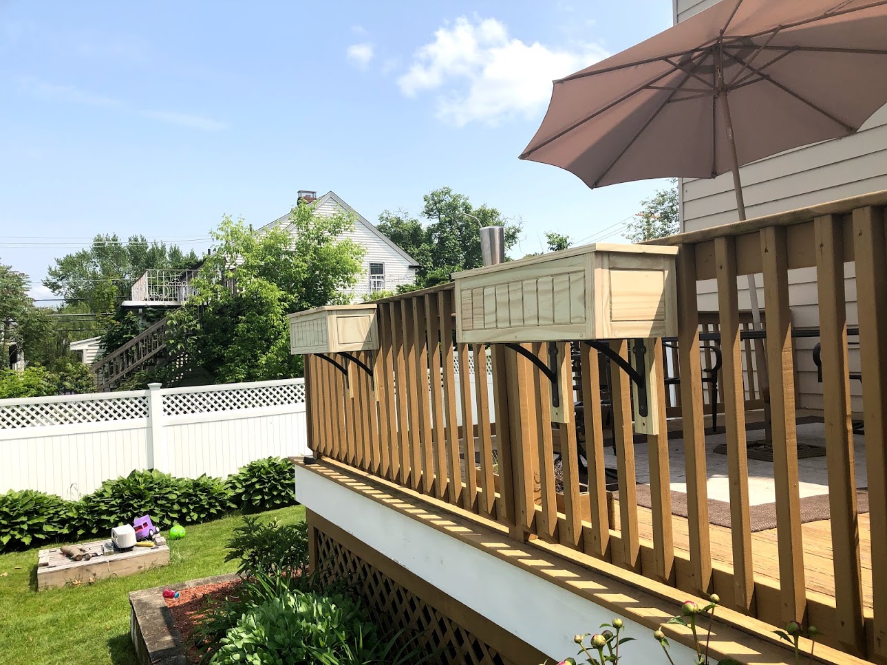
The pressure treated window box was made because I decided to make a few more and to be honest the cedar was such a difficult wood to work with as I got in the local home center anyway these windows bocxxes are basically made the same way as the Cedar one that I made with a few slight differences and that basically is they are only 24” long as I didn’t need them that long but the everything else is the same from the parts to the joinery and method of construction all the same.

These 2 window boxes were to be housed off the back deck in my back yard and will be mounted to the deck fence basically in the same manner as the cedar one I made for the front porch.

These window boxes also cost a lot less than the cedar and to be hones they look as good as the cedar one with a lot less of the construction headaches I had using the cedar.

IMG_1099.jpg
IMG_1097.jpg
IMG_1091.jpg
IMG_1095.jpg

I will be selling plans that I made to make these window boxes soon I just need to finalize them, well thanks for reading this article. I did make a project blog on making the larger cedar window box if you would like to read it I will leave a link below.

WINDOW FLOWER BOX : PHASE 6

Well with all the separate assemblies all complete its now time to make the sides, front 7 back into 1 box and that is what I will be doing in this final Phase of the project as well as a few other steps to ready them for the great outdoors.

Here is what I did in this Phase.

  • Predrilled for Screws

  • Glued Up the Box

  • The Removable Base

  • Made & Attached the Top Trim


PRE-DRILL HOLES

So to secure the base frame to the inside of the window I opted to use exterior grade construction screws going through the outside faces of the window box. So as I often do I counter-sunk screws theough pre-drilled holes then came back and added wooden plugs to hide the holes and screw heads. I used the same wood species of wood as the box so as that it would not be that noticeable.

IMG_1020.jpg
You can hardly see the cedar wood plugs they blend right into the faces of the box, just what I wanted.

You can hardly see the cedar wood plugs they blend right into the faces of the box, just what I wanted.

GLUE-UP

So the glue was pretty straight forward. A lot of the window box didn’t get any glue as I needed the panels in the front and sides to be floating in the grooves, that way it had the freedom to expand and contract with the seasonal humidity. So the only parts that got glue was the tenons on the ends of the rails all around the box.

IMG_1022.jpg
IMG_1023.jpg
IMG_1028.jpg

THE BOTTOM

The bottom couldn’t be any easier to make its basically a board cut to fit inside the walls of the window box, and to allow for water drainage I drilled 3 holes about 1-1/2” in diameter, later I came back and rounded over the holes using my palm router but sorry no picture. The bottoms basically sits on the base frame we made with the bridal joint in Phase 5, its not secured in any way.

ADDING THE TOP TRIM

There is just something very clean when trim is added to a project so I decided to add trim to the top of the window box and again I used cedar so as to make it blend in with the rest of the box. I mitered the corners at 45° using my chop saw and then used glue and brad nails to secure the 3 pieces to the top of the box. I didn’t use any trim to the back as it would not be visible. I also made some cedar wood putty to cover all the brad nail holes in the trim this is something I do periodically you basically use some very fine sawdust of the species of wood you are using and then add wood glue to the dust which creates a paste then basically apply the putty to the are let dry then sand away the leftovers and it hides everything.

IMG_1032.jpg
IMG_1036.jpg

Well that wraps up phase 6 phase of the project I really hope you liked this project blog and it gives you some inspiration in making your next project. Although this project deals with me only making the large 40” window box I did make 2 more smaller boxes but these box are different as they are smaller at 24” and I used pressure treated lumber for their construction.

ALL FINISHED

ALL FINISHED


WINDOW FLOWER BOX : PHASE 5

We are almost ready for the window box to get glued up but first I needed to create a base supports that they flower box bottom will sit on.

The Bottom support is made up of 4 pieces, 2 short sides and 2 long front & back pieces. I also changed up the joinery method to what is called a bridle joint. This joint is very strong and allows for more glue to be used where all the corners meet.

Here are the steps I took in making the bottom:

  • THE PARTS

  • WHAT A BRIDLE JOINT LOOKS LIKE

  • CUT THE BRIDLE JOINT

  • DRILLED SOME HOLES

  • TIME FOR DOWELS

  • GLUE-UP

THE PARTS

As you can see the bottom support has 4 pieces, 2 sides, front & back. The bottom support pieces are all joined using a bridle joint and you can see a closeup of the joint in this diagram. The actual bottom is just a piece of wood that is cut to size and just sits on this bottom framework. The bottom supports are basically held inside the window box using screws that I secured through the outside pieces of the box.

Screenshot - 5_28_2019 , 3_59_51 PM.png

THE BRIDLE JOINT

Here is the image of my bridle joint , yes I know its messy looking with all the glue and debris on the parts but its not sanded yet. If you would like to know how to cut such a joint I found a very useful article online hat will help.

IMG_1006.jpg

EXPLODED VIEW OF JOINT

Here is an image before I glued up the parts that make up the base support, you can see how the parts fit into each other. I accomplished this using my dado stack in my tablesaw to remove the different sections of waste that make the joint fit together. I am a big fan of this joint because its very strong and I needed it to be strong as a very heavy planter box will be sitting on it.

ADDING DOWELS

I also decided to add a dowel to the bridle joint to further strengthen the joint, this is very simple to do you basically drill a hole to fit whatever size dowel you will be using in my case it was a 1/2” diameter. so I drilled a through hole through one side of the bridle joint to the other side, then came back I tapped in my half wide dowel. Once the glue was added I came back with my flush cutting handsaw to trim both sides of the dowel and then sanded.

IMG_1009.jpg

ADDED THE DOWELS

Leaving the dowels proud of the surface gives me the opportunity to flush cut the dowels

IMG_1011.jpg

DOWELS FLUSHED TO THE FACES

Using my flush cutting saw I cut the excess dowel on both sides of the hole then used my sander to make everything nice and flush and smooth.

IMG_1013.jpg

BOTTOM SUPPORT ALL FINISHED

Here is the finished part, although this part will never be seen I am glad I took my time in preparing this part because what good is a box if a bottom falls out of it.

IMG_1012.jpg

THE BOTTOM PANEL

The bottom panel is basically a board cut to size and has 3 drainage holes cut into them.

IMG_1030.jpg

DRY ASSEMBLY

Now that all the parts of the box are all finished its time to see how all these parts are going to fit together, so I decided to do a little dry assembly to make sure everything fit the way I intended it to.

Here you can see how the back and front of the window box will fit into each other.

Here you can see how the back and front of the window box will fit into each other.

Well that wraps up phase 5 of the project and we are no ready for the next and final phase. In the next phase I will be gluing the window box sides together and adding the top trim to the box.

Catch you then.

WINDOW FLOWER BOX : PHASE 4

Phase 4 deals with the back of the flower box and its a pretty simple step. I could of done the back the same as the front but I opted just to use a solid wood panel for the back panel as it will not be seen since its going to be mounted to a fence.

Here are the Steps I took in making the back:

  • The parts

  • Joinery

THE PARTS

As you can see by the diagram the back panel is basically 3 pieces. Atop and bottom rail and a center panel. I chose to use a pressure treated panel for the back as it will not be seen but the rails are both made from cedar.

Screenshot - 5_28_2019 , 3_37_13 PM.png

THE BACK JOINERY

Basically the joinery is the same as the rest of the box. I added tenon’s to the left and right ends of both rails as that joint will be used to house the back into the left and right sides. Both rails also received a groove that will hold the center panel. The groove as you can see is centered on the rails thickness and is 1/4” wide x 3/8” deep. The back panel itself also has rabbet’s cut around all 4 sides of the panel on both the front and back faces this created a tongue that will then fit into the rails and sides of the window box.

Screenshot - 5_28_2019 , 3_41_09 PM.png

ALL MILLED UP

Here is an image of the back all milled out and ready to be glued together. The only parts of the back that are glued are the tenon’s on each end of the rails, the panel floats inside the grooves in the rails to allow for seasonal movement.

IMG_1015.jpg

EXPLODED VIEW OF BACK

Here is an image at a different angle of the backs components, you can also see the tongue that go around the entire perimeter of the panel. This panel doesn’t really get any glue until I am ready to glue the box together.

IMG_1014.jpg

Phase 4 is a wrap and it really didn’t take that long to do, there was not even a glue up to do as this does not happen until I am ready to do the window box glue up.

Next up is making the bottom supports and base

WINDOW FLOWER BOX : PHASE 3

So now that I have made both the left and right sides of the flower box Phase 3 deals with the Front of the Box. This phase probably has the most work since its the most visual piece of the box. In some ways the front bares some similarities to the sides in that it is basically a frame and panel design but with a lot more panels.

I broke this phase down into the following steps:

  • The parts

  • Joinery of the Stiles and Rails

  • Making the panel

  • Additional Joinery

  • Some Router Work

  • Assembly

THE PARTS

There are quite a few parts to making the front and they are:

  • Left & Right Stiles

  • Top & Bottom Rails

  • 10 Panels

    Below you can see the plans and the actual workpieces I needed to make the front.

Screenshot - 5_25_2019 , 2_23_51 PM.png
FRONT LABELED.png

JOINERY OF THE STILES & RAILS

CUTTING THE GROOVES

Just like I did in making the sides the front is basically the same, I needed to cut grooves on both rails and both stiles, the only difference in making the front is that the rails are a lot longer.

Although I am showing the rail in this image its because I need to cut a groove along the inside edges of the all parts. Basically a groove is cut on the center of the workpiece and is cut all the way along its edge.

The groove is 1/4” wide x 1/2” deep and centered on the workpiece thickness, although I thought the workpiece was 3/4” thick its evident here that its not but that was my problem to remedy and hopefully your stock is actually 3/4”.

To cut the groove I installed a 1/4” wide dado stack blade in my table saw and move the rip a 1/4” away from the blade.

The grooves are cut because I will be fitting the center panel inside this frame work .

IMG_0987.jpg

CUTTING THE RAIL TENONS

My next piece of joinery to do only applied to the rails as this is how I closed the panel off, I needed to cut a 1/2” long tenon. In this image you can see that I have my rails in a horizontal position and is back up by my miter gauge and sacrificial board to back up the cut (this reduces tear-out).

In my table saw I widened the dado stack to 1/2”, and lowered the depth of cut to 1/4” and made 2 passes on each end of the board and it revealed the tenon. This tenon is housed in the grooves that we already cut into the edges of the stiles.

front rail tenon.png

THE INSIDE PANELS

To complete the frame and panel front of course we need to make the panels as there are 10 of them in total, in the previous steps we created grooves on the inside edges of the rails and stiles, these were cut to house the center panel.

As you can see I have the panel laid flat on the table saw and in the saw I have a 3/8” wide dado stack raised a 1/4” high and a sacrificial board attached to the rip fence so I don’t damage my fence). Next I run all four edges on both faces of the panel to create a tongue, these tongues on all four sides of the panel get housed in the grooves.

Although there are a total of 10 panels that make up the front 9 of the 10 are the same but the last panel is different because there is no groove cut into the right side, instead it has a tongue so the difference from the other panels is that there is a centered tongue on all 4 sides of the panel so as that it can fit the stile on the far right hand side of the front assembly.

IMG_0931.jpg
Here is an image of how the panels all fit together.

Here is an image of how the panels all fit together.

ADDITIONAL JOINERY

Since I needed a method of joining the side to the window box back and front I needed to create a joint so as that when it came to gluing up the box everywhere had a home. So I needed to cut some more grooves. In this image you can see the left stile on its face about to receive the groove that the back will connect into. Again this groove is positioned a 1/4” from the edge and is again a 1/4” wide x 1/2” deep.

IMG_0981.jpg

ADDITIONAL JOINERY (Part 2)

You can see the connection pints that I needed to make to the front, As you can see I needed to cut an additional groove on the back side of right stile, this enabled the right side to be connected into the front assembly.

2.5.png

SOME ROUTER WORK

Although this is an optional step and could of simply left the side panel all flat and no character to it with a basic frame and panel design and sometimes I quite like that look. This time I decided that I wanted to define edges of the inside panel and make it stand out some more. So I used my router installed with a “V Groove” router bit.

THE STILES

These parts are some what more demanding because I don’t want to route the entire edge of the part, I only wanted the parts that came in contact with the panel visually. This is called a stop routing ad there are a ton of articles online on how to complete it the task.

IMG_0978.jpg

THE PANEL ROUTING

Routing the panel is easy enough as I just need to route the edges of the panel make sure your not routing the tongue as that will be hidden, add the router profile to what is left and will be exposed on the side. I just lowered the bit in the router table and just the right side of the bit is kissing the panel.

IMG_0997.jpg

ASSEMBLY

THE GLUE UP

The only part of the front assembly that was to receive glue was the tenons on the top and bottom rails, this is because I wanted the panels inside the frame to be able to move, as I already documented season humidity can shrink and expand wood so as to avoid the panel splitting it moves freely within the rails and the stiles.

CLAMPING THE PANEL

Here you can see the front panel all assembled and the glue applied to the tenon’s, I used a decent amount of clamps to keep everything aligned and in the end I will have a very decorative front panel .

IMG_0995.jpg

Well that wraps up Phase 3. I now have both sides and the front completed, all that is left to do is to make the back and bottom framework and then it will all be ready for the assembly phase.

WINDOW FLOWER BOX : PHASE 2

Phase 2 of the project deals with the Left & Right Sides. Basically the sides are made from 5 parts and if your familiar with Frame & panel construction you can make them easily.

I broke this phase down into the following steps:

  • The parts

  • Joinery of the Stiles and Rails

  • Making the panel

  • Additional Joinery

  • Some Router Work

  • Assembly

THE PARTS

The side is made up with the following parts:

  • Left & Right Stile (Vertical Pieces)

  • Top & Bottom Rails (The Horizontal Pieces)

  • 1 Panel (Basically the inside of the frame)

Here you can see the left side and its labeled parts, the right side has the same parts but the joinery positioning is a little different, but Ill get to the joinery a little later.

Here you can see the left side and its labeled parts, the right side has the same parts but the joinery positioning is a little different, but Ill get to the joinery a little later.

JOINERY

The stiles are the left and right vertical pieces of the side and these all need a groove cut into the edge of the boards thickness spanning the entire length of the part. Although I will cutting the same groove into these parts its crucial that you place the groove on the correct edge or the joinery will not come together to wrap the panel and house the rails.

CUTTING THE GROOVES

Although I am showing the stiles and rails in this image its because I need to cut a groove along the inside edges of the all parts. Basically a groove is cut on the center of the workpiece and is cut all the way along its edge.

The groove is 1/4” wide x 1/2” deep and centered on the workpiece thickness, although I thought the workpiece was 3/4” thick its evident here that its not but that was my problem to remedy and hopefully your stock is actually 3/4”.

To cut the groove I installed a 1/4” wide dado stack blade in my table saw and move the rip a 1/4” away from the blade.

The grooves are cut because I will be fitting the center panel inside this frame work .

IMG_0933.jpg

CUTTING THE RAIL TENONS

My next piece of joinery to do only applied to the rails as this is how I closed the panel off, I needed to cut a 1/2” long tenon. In this image you can see that I have my rails in a horizontal position and is back up by my miter gauge and sacrificial board to back up the cut (this reduces tear-out).

In my table saw I widened the dado stack to 1/2”, and lowered the depth of cut to 1/4” and made 2 passes on each end of the board and it revealed the tenon. This tenon is housed in the grooves that we already cut into the edges of the stiles.

IMG_0937.jpg

THE INSIDE PANEL

To complete the frame and panel side of course we need to make the panel, in the previous steps we created grooves on the inside edges of the rails and stiles, these were cut to house the center panel.

As you can see I have the panel laid flat on the table saw and in the saw I have a 3/8” wide dado stack raised a 1/4” high and a sacrificial board attached to the rip fence so I don’t damage my fence). Next I run all four edges on both faces of the panel to create a tongue, these tongues on all four sides of the panel get housed in the grooves.

IMG_0932.jpg
Here you can see the profile of the panel, the top and underside of the panel is removed creating a tongue.

Here you can see the profile of the panel, the top and underside of the panel is removed creating a tongue.

ADDITIONAL JOINERY (Part 1)

Since There are 4 sides to any box I needed a housing method to find homes at all 4 corners of the box, in this illustrated diagram you can see the left and right stiles (pink) and where I needed to locate the groove and tongue so as that I could complete the joinery of the back and front of the box

additional joinery 2.0.png

ADDITIONAL JOINERY (Part 2)

Since I needed a method of joining the side to the window box back and front I needed to create a joint so as that when it came to gluing up the box everywhere had a home. So I needed to cut some more grooves. In this image you can see the left stile on its face about to receive the groove that the back will connect into. Again this groove is positioned a 1/4” from the edge and is again a 1/4” wide x 1/2” deep.

IMG_0981.jpg

ADDITIONAL JOINERY (Part 3)

I am most definitely jumping ahead using this image but you can see the connection pints that I needed to make to the sides, The left side stile shows a tongue and the right side stile shows the groove this is how I attached the front and back of the box to the left and right sides.

additional joinery 3.0.png

Here is the completed side panel with the router groove all cut into the center of the assembly.

Here is the completed side panel with the router groove all cut into the center of the assembly.

SOME ROUTER WORK

Although this is an optional step and could of simply left the side panel all flat and no character to it with a basic frame and panel design and sometimes I quite like that look. This time I decided that I wanted to define edges of the inside panel and make it stand out some more. So I used my router installed with a “V Groove” router bit.

THE PANEL ROUTING

Routing the panel is easy enough as I just need to route the edges of the panel make sure your not routing the tongue as that will be hidden, add the router profile to what is left and will be exposed on the side. I just lowered the bit in the router table and just the right side of the bit is kissing the panel.

THE STILES

These parts are some what more demanding because I don’t want to route the entire edge of the part, I only wanted the parts that came in contact with the panel visually. This is called a stop routing ad there are a ton of articles online on how to complete it the task.

Here is an image of the “V GROOVE” bit in the router.

Here is an image of the “V GROOVE” bit in the router.

Here you can see the subtle little groove cut on the right side edge, but boy does it make a difference.

Here you can see the subtle little groove cut on the right side edge, but boy does it make a difference.


ASSEMBLING THE SIDES

Assembling the side was a pretty simple affair I basically applied glue to the tenons on the rails and installed them into the left and right stiles. This is the only glue that I applied to the entire side and there is a good reason. I wanted the inside panel to have freedom of movement because of seasonal humidity, these climate changes can break apart a project because wood expands and contracts within different seasons, and I needed the center panel to have that freedom to move within the frame work.

ORIENT THE PARTS

I usually do a dry assembly of the parts and rehearse the glue up, but this wasn’t really necessary as the glue up was small.

IMG_0973.jpg

ALL CLAMPED UP

Here you can see both the left and right sides all glued and clamped up I left this to dry overnight.

That wraps up Phase 2 of the project and the sides came out ok I was happy enough with them but this cedar is proving difficult but I am satisfied with how they came out. Next up is assembling and making the front of the box, this phase most definitely has the most work to it but it has a lot of similarities to the sides as it is just a much bigger frame and panel.

WINDOW FLOWER BOX : PHASE 1

With Summer around the corner I decided to make some new window boxes, I am using Cedar wood on the first box and see how I fair with it. To be honest the Cedar wood that I get from the bog box store isn’t usually that great, but I really love the look and smell of the wood.

I needed to make a total of 3 boxes with 36” & 24” widths I will be using plastic liners to put the actual plants into so I made my box dimensions according to that.

To be honest I could of made quick work of this project and basically screw 4 boards together and screw in a base and call it a day, but in keeping with my fine woodworking endeavors I chose a more elaborate design.

WINDOW BOX FEATURES

  • Frame and Panel design

  • Tongue & Groove Joinery

  • Top Trim to cover all the exposed joinery edges.

  • Rail, Stile & Panel construction techniques.

As I usually do I will be breaking this project down in the following parts:

  • Research & Design

  • Materials Needed : 36” & 24” Sizes

  • PHASE 1: First Things First : Ripping & Crosscutting

  • PHASE 2: The Sides

  • PHASE 3: The Front

  • PHASE 4: The Back

  • PHASE 5: The Base

  • PHASE 6: All Finished

RESEARCH & DESIGN

Although I did quite a lot of research online I could not find exactly what I wanted in 1 project so anytime that happens I design the project on Sketchup and tweak certain things to make it my own. The window boxes do contain certain characteristics of some project that I found online but all in all this is my design. I was originally going to use sliding dovetails as the primary joinery method but after purchasing the cedar I decided against it as the cedar was not exactly 3/4” and I wanted to use a 1/2” dovetail bit. The cedar was 1/8” narrow than 3/4” and it was quite brittle so I decided to go with tongue & groove joinery.

Below you can see my Cover page Images, I did make a very detailed set of plans to help make this project and these are what the window box will look like. This blog details me making the 36” Cedar Window Box. The 24” wide window box will not be made using Cedar, Ill explain later. But both boxes will be made using the same joinery and woodworking techniques.

Screenshot - 5_23_2019 , 3_11_38 PM.png

MATERIALS NEEDED

So like I said I will be making 2 sizes of window box and here is what you need to make either size.

36” WINDOW BOX

  • 12 FEET OF CEDAR

  • 8 FEET OF PRESSURE TREATED LUMBER

  • TITEBOND III GLUE (or any waterproof glue)

  • 1 5/8” Stainless steel screws

24” WINDOW BOX

  • 16 FEET PRESSURE TREATED WOOD (Didn’t use Cedar)

  • TITEBOND III GLUE (or any waterproof glue)

  • 1 5/8” Stainless steel screws

Here a the materials that I needed to make the window box.

Here a the materials that I needed to make the window box.

Here is the wood glue and steel screws, I wont need that many screws maybe 10 or so.

Here is the wood glue and steel screws, I wont need that many screws maybe 10 or so.


FIRST THINGS FIRST : RIPPING & CROSSCUTTING

The way that I designed the window box looks awesome but it has one downside there are so many pieces to rip and crosscut. I even set up my cultist into so many sections I had to number my boards so Icut the correct components of the correct boards, but once I got going I made quick work of this. I think when I was done I had almost 40 parts to the project.

RIPPING

I made sure to keep all my board widths the same and that was a 1-1/2” wide so I followed my cut list ripped all the boards into easier to manage strips. In this image you can see my tablesaw set up to cut 1-1/2” cuts. For those of you that are not aware with some of the terminology, Rip cuts are long cuts made with the grain, and crosscuts are those cut across the grain.


IMG_0922.jpg

RIPPING (PART 2)

Here you can see the cedar sections ripped to 1-1/2” wide there are some wider cuts to make but they are for the back and bottom of the box and a few other components. If you use my plans to make this box all these are laid out for you. To make sure that I knew what board went with what cut list diagram I placed my actual plans on the appropriate boards, so when it came to crosscutting them to final size I had a guide to help me.

IMG_0921.jpg

CROSSCUTTING

I am lucky enough to have a dedicated miter saw station that really comes in handy when I have a ton of repeat cuts, here you can see my miter saw with a stop block set to the desired length that way I just place my stock against the stop block and cut to hearts content, there were a few different lengths that I needed so I just cut all boards that were the same size and then adjusted the stop block for the next size on the list, this way you can guarantee the pieces are of uniform length.

ALL CEDAR PARTS ARE DIMENSIONED

Here you can see all the cedar parts to their final dimensions and again you can see my cut list plans under some of the parts so as that I know what each part is for. I did still need to work on the pressure treated wood but I decided until the window box frame was finished before I cut that up.

IMG_0969.jpg

CHANGE UP; NOTIFICATION

Well Phase 1 is all wrapped up and I well on the way of making some pretty stunning window boxes. Before I go further with this blog, I just wanted to let you know why I chose not to use cedar on the smaller boxes and that was because it was a nightmare to work with, the cedar was under dimensioned it was supposed to be 3/4” thick but realized it was 5/8” thick and played havoc with my joinery dimensions, this resulted in some joints far too loose and some too tight because I usually deal in thirds when tongue and grooving, this under dimensioned stock resulted in some pieces cracking as the wood was extremely light and had little robustness to it. So although I completed the window box and it looks great, it should have gone a lot easier and a lot less hair would have been pulled out. So if you choose to make the window box out of cedar make sure that it is at the least 3/4” thick, thicker would be better. But there you go.

Newsletter Discontinued

Hi Everyone, 


I just wanted to let you all know that my Monthly Newsletter is getting shelved for a while . To be honest I don’t have the time to keep making it for a few subscribers . But I will be keeping the blog posts coming.

Id like to take the opportunity to thank everyone who did subscribe to my monthly newsletter and who knows it be back at a later time.

Thanks Again 

Ed

SCRAP- WOOD STORAGE CART : PHASE 4: ALL FINISHED

THE ASSEMBLY


IMG_0844.jpg
IMG_0845.jpg


THE ASSEMBLY


The assembly was done in the following sequence.

  • Attached the vertical shelving unit to the base

  • Attached the back to the cart

  • Attached the Central storage cubby unit

  • Attached the front

ADDED GLUE TO THE BASE

Before I secured the shelving storage unit to the base I added glue to the cart base. This would secure that even if the pocket hole screws failed the unit would still be secured to the cart.

IMG_0830.jpg

VERTICAL SHELVING UNIT

I positioned the shelving unit onto the cart and squared it up with the corners of the base.

IMG_0833.jpg

POCKET HOLE SCREWS

Since I already drilled the pocket holes into the shelving unit all that I needed to do was to add the screws and drill away securing the unit onto the cart base and that’s it. The glue will do the rest.

IMG_0832.jpg

ATTACHED THE BACK

Now that the shelving unit was attached I could proceed to attaching the back to the cart. A you can see I added plenty of glue to the back edge of the cart from the squeeze out, I used some pocket hole clamps to secure the back temporarily to the shelving unit and drove home all the screws into the base and the shelving unit.

Here you can see a close-up of the pocket hole clamps securing the back to the shelving unit, these clamps are the extra set of hands I needed to secure the back. Now you see why I added the vertical shelving unit first as I needed somewhere to secure the back panel

IMG_0835.jpg
IMG_0836.jpg

LAYOUT LINES

Now it was time to switch my attention to installing the center cubby unit. Before I could attach the unit I first lay the cubby onto the base and position it according to the plans, Then I made some pencil marks so as that I know where to add the glue.

ATTACHED THE CUBBY UNIT

With the cubby now sitting on the base with the glue spread onto its footprint I went about securing the cubby with you guessed it pocket holes. I cant really show any pictures of that but you can guess what it looks like from the countless pictures I have taken of making the pocket holes. Its finally looking like a cart.

IMG_0842.jpg

ADDED THE END CAP

This little piece of plywood is what sections off the end of the front panel, is flush with the end of the center cubby divider. As you can see I secured using pocket holes and glue, but I attached this before I secured the front of the cart, although the pictures show the front in position I forgot to take a picture before doing this step.

IMG_0849.jpg

INSTALLING THE FRONT

All that was left to do was attach the front panel to the cart, I really love this concept its basically a very shallow storage area that is about 48” long but its only 6” wide. But it allows me to store so many different pieces as the time goes by. As the rest of the cart I applied glue to the bottom or cart base and then secured the front with the pocket holes and screws that I have done already. I added all the pocket holes on the inside faces of the project so as that they would not be visible from the outside of the cart.

IMG_0844.jpg

ALL FINISHED


Well that wraps up Phase 4 and the cart is also completed. I really love how the cart came out, its mobile and can be moved easily around the shop although I don’t think it will be move much except when I need to get access to the panels stored in the back of the cart. I also love the shelving storage unit I am keeping most of the small solid wood offcuts that are in abundance in the shop and it will be really nice in having a nice organized way of storing them. Although I made something like this cart a few years ago it didn’t have this added storage unit and the cart is all the more functional for it.

Before I close off this project I wanted to show a before and after picture so as that you can see how much this cart can actually hold. Until the next project take care and Ill catch you the next time…

BEFORE THE NEW CART

IMG_0846.jpg

AFTER

IMG_0856.jpg

Scrap - Wood Storage Cart : Phase 3

Here are the parts I will be working on in Phase 3, The Back, Front and the Cart Base.

Here are the parts I will be working on in Phase 3, The Back, Front and the Cart Base.

Phase 3 deals with the cart Base, Front and Back. This section is the final section where I will be cutting the final components of the cart before I start my assembly.

Here are the tasks that I completed in this section:

  • The Base and Casters

  • The Back and Pocket Holes

  • The Front


THE BASE & CASTERS


THE BASE & CASTER WHEELS

The base is pretty basic stuff but its role in the cart is crucial. The base is what all the other components that I made sit on, so it needs to cut to the exact size in order for everything to fit on it. As far as skill needed to create the base its very basic stuff but here is the order of events that went into prepping it.

IMG_0825.jpg

REINFORCING THE CASTERS

4 Plywood squares and screw them into the underside of the base. These square reinforce the corners of the base where the caster will be position. I also countersunk 4 screw holes where the screws will be inserted to secure it to the bottom of the cart. Then I used glue and screws to secure it.

IMG_0819.jpg

SECURING THE CASTERS

To secure the casters to the squares I just screwed to the cart base, I used 4 Hex Head Sheet metal screws into the 4 holes of the casters. I really like these Hex Head screws because I can use my drill to attach them using a head bit in it. I used to use bolts , washers & nuts to do this but I hated that I needed the bolts to protrude through whatever base I was adding casters to then securing the caster in position with nuts. With these screws they do not protrude through the base and they are out of sight. Some time whatever you are attaching them to get in the way of other components.

IMG_0823.jpg
Here are the hex screws I was referring to.

Here are the hex screws I was referring to.

2 DOWN : 2 TO GO

Here is the second caster I added all that was left was to add 2 more on the front end of the cart, and basially the cart base is ready.

IMG_0818.jpg

THE BACK


The back of the cart is basically a plywood panel that is secured on the back edge of the base, this panel defines the sheet goods storage space that I am building into the cart. In hindsight I wish this space was wider, because at 6” deep it really doesn’t cater to storing that much storage space, but anyway hindsight is a beautiful thing. The panel is basically a quarter sheet of plywood with pocket holes all the way along the long edge so as that it can be screwed into the base of the cart, I also positioned pocket holes on the back edge so as that I can secure the panel into the vertical shelving rack I built in phase 1.

THE BACK PANEL & POCKET HOLES

Here you can see the back panel which is 48” x 24” in size, you can also see all the pocket holes that I drilled on the bottom & back edge so as that I can secure the panel into the cart.

IMG_0811.jpg

THE FRONT

Basically the front is a long piece of plywood that is positioned on the front of the cart, as you can see in the image there is very little to it. I basically cut the panel to 48” x 6” wide. But what you don’t really see is that I have drilled pocket holes into the back face of the plywood panel in order to secure into the base. Basically anything that is being secured into the base is pocket hole screwed with glue.

LABELED FRONT.png

PHASE 3 COMPLETE


Phase 3 basically wraps up all the table-saw work, all the pocket hole drill and basically all components are ready to be assembled into 1 pretty well organized cart. All of these phases could of been stand alone projects on their own. So lets recap we have made a vertical shelving unit with 4 shelves, a cubby with 4 compartments to store wood in, a base where we added casters.

All that is left to do is assembly and that will be Phase 4 pf the project.

Scrap WoodStorage Cart : Phase 2

PHASE 2

Central Storage Section.png

The second phase of the scrap wood storage cart dals with the central storage option. This is basically a bunch of cubbies that I plan on standing lumber in vertically.

The storage unit basically has 2 sides and 4 cubbies . The sides of the cubbies is angled from the back to the front.

Here is the order in which I made the cubby

  • Breakdown plywood panel

  • Cutting the Dado’s in the side panels

  • Pocket Holes

  • The Dividers

  • Assembly

  • Finish Phase 2


BREAKING DOWN THE PLYWOOD PANELS


SETTING UP

I needed to set-up a working area as the plywood panels were kind of big. I purchased some foam insulation board as a sacrificial surface to lay my workpiece on, that way I cut through the plywood and not damage anything when using my circular saw. Here you can see the sawhorse with a plywood on top then I laid my pink insulation board on top of that.

IMG_0776.jpg

BREAKING DOWN THE PANEL

In this image you can see the plywood panels with some layout lines and my straight edge on top of the plywood to guide the circular saw. As you can see the plywood panel will be angled (27” at its highest side & 12” at its lowest) all that was left to was to cut the plywood and it came out great.

IMG_0778.jpg

PLYWOOD SIDES CUT TO SIZE

Here are the 2 sides of cubby unit and as you can see they are angled. I also took the opportunity in laying out the dado cuts which the dividers will sit in.


JOINERY


CUTTING THE DADO’S

In this image you can see the plywood side with my dado router jig on top and I used my plunge router installed a 3/4” router bit to remove the material. The depth of the dado is 1/4”. The idea of the dado jig is to align the router using guide rails screwed together and then clamped to my table to guide the router through the workpiece. There was a total of 3 dado’s and 1 rabbet at the front of the side (12” high end).

IMG_0784.jpg
A close-up of the dado jig

A close-up of the dado jig

COUNTER-SINK & POCKET HOLES

I decided to pre-drill all the holes for the unit now rather than after the unit was assembled. I positioned counter-sunk holes in the outside face of the side, this was done to help me position the screws which will secure the plywood dividers that make up the cubbies. To kelp me pre-drill I used a very small diameter drill bit and drilled through the inside groove then came back and flipped the side over to its outside face and used my counter-sinking bit to finish the hole off. The counter-sink bit helps bury the screw inside the plywood that way the screw isn’t that visible.

POCKET-HOLES

I also placed pocket holes on the inside face of the sides this was the method I chose to secure the unit onto the base of he cart. I drilled pocket holes on the bottom and back of the panel. This enabled me to also secure the unit the right side of the vertical storage unit I just made.

IMG_0797.jpg
Pocket Holes Applied

Pocket Holes Applied


THE DIVIDER PANELS


THE DIVIDER PANELS

The divider panels are what I used to separate once cubby from another. Since the sides of the unit are tapering from back to front, I needed to cut these panels on the table-saw in decreasing heights in order to match the profile of the sides of the unit. (All these dimensions are in the plans)

IMG_0792.jpg

ASSEMBLY TIME


ASSEMBLY TIME

The process I used in the last glue up was the same in this glue-up. Here are the steps I took in completing the central storage unit.

  • I placed the right hand side panel on its back making sure the grooves were facing up. I applied the glue into the grooves.

  • Next I added the divider panels making sure hat they were placed in sequence according to their height so as to match the profiled slanting on the side panel.

  • Next I added glue to the tops of these dividers, then placed the left hand side panel with the dado grooves facing down, and screwed the panel in place. I needed to use clamps to keep the panel tight to the divider panels.

  • Finally I flipped the whole unit over onto the right hand side of the unit and then added the final screws completing the assembly. The screws were a great solution as I didn’t want clamps all over the unit and they worked great.

IMG_0802.jpg
IMG_0803.jpg

PHASE 2 COMPLETED


Here is the finished central storage unit. I love that it is tiered which allows functional storage for different lengths of lumber

Here is the finished central storage unit. I love that it is tiered which allows functional storage for different lengths of lumber

Here I both unit as hey will appear in the final cart

Here I both unit as hey will appear in the final cart

Scrap-Wood Storage Cart : Phase 1

This is the section of the cart that I will be working on first, The Vertical Storage Shelves. Its the brown highlighted section.

This is the section of the cart that I will be working on first, The Vertical Storage Shelves. Its the brown highlighted section.

As I mentioned in my previous post I will be tackling this project in 4 phases, this is the first of 4. Before I head into this part let me first breakdown what I will be writing about in this post.

  • Research & Design

  • Materials & Tools

  • Left Side Panels

  • Shelves

  • Pocket Holes

  • Vertical Shelf Unit Assembly

The cart has a ton of storage within a small footprint, this shelving unit that I am making has a decent amount of work to make it, I will be using pocket hole joinery ,dadoes, screws and glue to assemble it. So lets start.

RESEARCH & DESIGN

I wish I could claim credit for this design but I was not the one who designed it. I came across this project on Pinterest and the original design came from DIY Montreal, you can find her website in the link and she also has free project plans to help make it. She also documented a project video on YouTube and you can wtch it below.

As far as design I did also complete my own set of plans for this project and I will also post these free plans on my site after the project is completed. But you can see my Plans Cover page below. I designed my plans on Sketchup like I almost always exclusively do.

Screenshot - 5_7_2019 , 8_16_52 PM.png

MATERIALS NEEDED

This project requires the following materials & tools in order to make the cart. Ask the home center to break down the 2 big plywood sheets, they are available in both sets of plans.

  • (2) Full sheets of 3/4” plywood

  • (4) 3” Casters

  • Wood Glue

  • 1-1/4” wood screws

  • 1-1/4” pocket hole screws

  • #12 3/4” Hex Head Slotted Sheet Metal Screws (I use these to secure the casters to the base)

TOOLS NEEDED

  • Tablesaw

  • Dado Stack

  • Skill Saw

  • Router

  • 3/4” Straight router bit

  • Router Dado Jig

  • Pocket Hole Jig ( I used the Kreg K4)

  • Drill & Driver

Here is the 2 sheets of plywood cut down to manageable pieces, I had this done at the home center.

Here is the 2 sheets of plywood cut down to manageable pieces, I had this done at the home center.

Here are the 3” casters & Screws. I also have my trusty plans to help me build this project especially to help me with dimensions of the various parts of the cart.

Here are the 3” casters & Screws. I also have my trusty plans to help me build this project especially to help me with dimensions of the various parts of the cart.


VERTICAL SIDES

The vertical storage sections is basically made up with 2 sides and 4 shelves, the shelves are secured with glue and screws into the dado’s that were cut using a dado stack installed into my tablesaw

LAYOUT

When I was at the home center I had the plywood boards cut into certain sizes, I did this to cut down on the work I had to do and this is one of them boards, this boards measures 48” x 36” this was cut to these dimensions as I could cut the dado’s all at once, the dadoes are placed 8-1/4” away from each other into 1 panel and then cross cut the panel into the 2 sides. I did this because I wanted to guarantee that all the dado’s measured up when it came to installing the shelving. As you can see I used pencil marks to position where I wanted the dado’s to be cut on the tale saw.

IMG_0758.jpg

CUT THE DADO’S

Here you can see the same panel with all the dado grooves cut into where I had previously made my layout marks. These dado are places 8-1/4” away from each other, thus giving me equally spaced shelving. But still notice that it is still one panel. To cu the dado’s I used my 23/32” wide dado stack in my table-saw and cut the dado to a 1/4” deep.

IMG_0759.jpg

CROSSCUT THE SIDES

Now that the dado grooves were cut into the board I was able to crosscut the boards that will ultimately become the 2 sides of the vertical shelving unit on the cart. I installed my 60 tooth table-saw blade into the saw and crosscut and as you can see the dado grooves all line u with each other.

IMG_0760.jpg

COUNTER-SUNK TIME

Since I will be using glue and screws to secure the shelves into the dado grooves, I decided to place all these holes now as it would be a quick process. So I used my drill installed with a counter-sunk bit to place 2 holes on either side of the panel.

IMG_0761.jpg

POCKET HOLE TIME

I will be using pocket hole joinery in certain parts of this project, here I am placing pocket holes in the bottom outside faces of the vertical side panels, this is how I will be securing the shelving unit to the base of the cart. Here you can see me using the Kreg K4 jig , I like using this method sometimes as it is quick and I don’t need a lot of big clamps to secure the workpiece as I wait for the glue to dry. This method allows me to keep working on the project.

IMG_0764.jpg
Here is the front side of the jig

Here is the front side of the jig

SIDE PANEL

Here you can see one of the side panels all outfitted with counter sunk holes and pocket holes all ready for the assembly phase, which will be soon.

IMG_0766.jpg

DRY ASSEMBLY

In this image you can see that all the shelves have been cut, there is nothing to do with these panels other than to cut them to the plan dimensions which is 24” x 11’. I am putting them into the dado grooves that were cut earlier and making sure that they all line up.

IMG_0768.jpg

ASSEMBLY TIME

All that was left to do was to assemble the shelving unit. These are the steps I took to assemble the unit.

  • I place one of the sides flat onto my assembly table with the groove side up, I placed glue into all 4 grooves and then installed the shelves into the grooves, but no screws yet as I don’t have access to this side as it is laying on the table.

  • Next I placed the mating side piece onto the shelves this time with grooves facing down, after adding flue to the edges of the shelves I use my 1-1/4” screws to secure the side panel onto the shelves.

  • All that was left was to flip the shelf unit over and secure the other side panel with the 1-1/4” screws, and that was it.

Here you can see the shelves sitting in the dado grooves, these shelves are not going anywhere. I will need to sand the unit down but its made.

Here you can see the shelves sitting in the dado grooves, these shelves are not going anywhere. I will need to sand the unit down but its made.

I had some difficulty getting this unit square and it had nothing to do with my layout work or even my screw placement, I discovered that the plywood panel that these pieces were cut from had a bow to the panel, be careful selecting plywood from big box stores as they sometimes are not the flattest. In the end I managed to get everything square and plum.

Well this wraps up Phase 1 of the project build and next I will be working on the central storage bins for the cart.. catch you then.

Scrap - Wood Storage Cart Build

As most woodworkers realize how impossible it is to keep your lumber supplies organized. Over the past 5 years I have created so many projects in my attempt to solve this dilemma and to be honest some of them worked for a while and others failed miserably.

At the present moment I have 3 units that I currently fit all my scrap lumber and sheet goods into and they take up a decent amount of room in the shop. So I decided to try and fit all my scrap wood and sheet goods into 1 unit and alleviate some of the space that my current set up is taking up.

I will be breaking this project into 3 sections and they are:

  • PHASE 1 : Building the Vertical Storage Unit

  • PHASE 2: Building the Central Storage Section

  • PHASE 3: The Base, Front & Cart Back

  • PHASE 4: Cart Assembly

Screenshot - 5_7_2019 , 8_16_52 PM.png

PHASE 4: ASSEMBLY


OPENING BLOG

Like I usually do in big projects I break the project down into manageable parts and to the same degree I blog about each part in the same manner. Below is the sequence of events and activities I do to make the cart.

  • Research & Design

  • Materials Needed

  • Phase 1: Building the Vertical Storage Unit

  • Phase 2: Building the Central Storage Section

  • Phase 3: The Front, Back & Base

  • Phase 4: Assembling the Cart

This is what I will be making, on the left side of the cart is a vertical storage unit with 4 shelves, in the middle is a central storage area with 4 bins, on the back is a slot to store my sheet goods and in the front will be a shallow cubby to store my odds and ends.

00B399CE06A36A7E0486A2D202C9F6291CBDFDDE830F32B1.jpg
F6NO1FBJ7KQPDZU.jpg

WIFI ROUTER BOX

During the week I decided to re-organize the home office and in doing so needed to place the WIFI router box, but I didn’t have anywhere to really put it so I had to put the hideous looking box on the edge of one of the desks. So I decided to make a storage container to try and hide it in plain sight.

I didn’t really do much in the line of research on this but I did design it on my computer using Sketchup. I took the Router box’s dimensions and used them to come up with a storage box that I could store it in whilst stll sitting on the edge of the desk.

Here is how I made it:

  • Design

  • Materials Needed

  • The Parts

  • The Sides

  • The Base

  • The Back Slats

  • The Top

  • The Front Cover

  • All Finished

THE DESIGN

As I had mentioned I took the router box dimensions and used them to design what I wanted. The container is approx. 11” high x 6” wide x 9” deep. The joinery used to attach the base to the sides is a good old fashioned Tongue & Groove joint. The lid is held in place by 4 dowels that were inserted into the top edge of each side. The back slats have a half-lap joints into the back edges of the both sides of the box. The front is where it gets interesting, I designed a grill type front but because I need a way to access the router from time to time I am using magnets to keep it attached until I need to remove the lid.

I needed to make sure that the box had enough ventilation so as to let air moving around the WIFI box and that is why I placed a grill type front on the box. The left hand side has a oval shaped hole so as to let the wires and internet cable pass through the box to the router box.

Here you can see the 3D model of the storage box. The left hand side of the box has a big oval window so as that the wires can be fed through tp the router.

Here you can see the 3D model of the storage box. The left hand side of the box has a big oval window so as that the wires can be fed through tp the router.


MATERIALS NEEDED

This project doesn’t require much in the line of wood in fact you could make it out some scrap wood if you any. I used most of my scrap so I needed to purchase the following

(1) 1” x 12” x 8’ of pine board and there will be decent of scrap wood left after you have completed the project.

(4) 1/4” wooden dowels

(8) 1/2” diameter magnets

Wood glue

Here is the length of 1” x 12” that I got at my big box store

Here is the length of 1” x 12” that I got at my big box store


THE PROJECT PARTS

There are a total of 8 parts to making this storage box and they are, you can see the parts in the image below, as you can see they are not that big

  • Base

  • Left Side

  • Right Side

  • Top

  • (3) Back Slats

  • Font Cover

parts.png

THE SIDES

Although there are 2 sides to this project there are some difference between them so I will start describing “The Left Side “ then move onto the right.

I decided to start with the left side as that was one of the pieces that needed the most work. The left side has an oval hole that is cut into it, and that is to allow the various wires to pass through the box into the router.

THE LEFT SIDE


STEP 1: LAYOUT

As you can see I did a decent amount of layout, The center marking are the dimensions for laying out the oval hole I want to cut out. The “X”s on the left side indicate where the back slats are going to be positioned with the half-lap joint later on.

IMG_0661.jpg

STEP 2: REMOVING THE HOLES

Here you can see the left side on the drill press, the drill press has 2” diameter hole saw this is used to remove the hole which create the arc on the top and bottom of the oval hole that I want to create.

IMG_0664.jpg
IMG_0663.jpg

STEP 3: REMOVING THE WASTE

With both holes remove I can now use my jigsaw to remove the material left between both holes, this create the rough outline of the oval shape that I am looking for.

IMG_0665.jpg

STEP 4: SANDING

With the material removed from the side it is time to clean up the inside edges of the oval hole and to that I used my Oscillating Spindle Sander to clean up all the very rough edges left by the jigsaw.

IMG_0667.jpg

STEP 5: ROUND-OVER (Optional)

Although this step is optional I decided to use my palm router to add a round-over profile to the oval hole that I just made, I wanted this edge to be smooth because it will have wires going through there and I didn’t want them getting damaged. I also think it adds a nice touch to the project.

IMG_0669.jpg

THE RIGHT SIDE


THE RIGHT SIDE

The right side is quick work mainly because There is no oval hole that we need to cut out as we did with the Left Side. Basically all that we needed to do was:

  • Cut is to size

  • Cut the groove in the bottom so as that we can mate it with the base later on.

  • We also need to remove the half lap grooves so as that the back slats can be mounted inside these grooves. But if you remember I did that already when doing the left side as I did them both together.

IMG_0670.jpg

CUTTING THE HALF LAP JOINTS

Although there are a few difference between both sides, there is one common trait that they both have. They both need grooves cut on the back edges of the sides, this is so I can attach the half-lap back slats into them, these back slats are what help keep the little box together by joining both sides to each other.

WHAT IS A HALF LAP JOINT ?

A lap joint or overlap joint is a joint in which the members overlap. Lap joints can be used to join wood, plastic, or metal. A lap joint may be a full lap or half lap. ... In a half lap joint or halving joint, material is removed from both of the members so that the resulting joint is the thickness of the thickest member.

17774e8047fda68434730d35ec7a5d7d.jpg

HOW DID I CUT THEM?

I cut the grooves out by doing the following:

  • I placed a 3/4” thick dado stack into my table-saw and raised the blade to 3/8” high

  • Then I placed my miter gauge on the table-saw and clamped both side pieces to the miter gauge fence.

  • Using my layout lines as guides I carefully remove the wood in both side pieces simultaneously this way I could guarantee that both side pieces would be the same.

IMG_0681.jpg
IMG_0684.jpg

FINISHED GROVES

Here you can see both sides with the grooves or notches cut out, these notches are 3/8” thick as that is half the thickness of my 3/4” thick pine pieces and the oak back slats I will be attaching in these grooves.

IMG_0685.jpg

THE BASE


CUTTING THE TONGUE’S

The base is also another board that will not take long in preparing, all I needed to do was to cut the mating tongues on the left and right sides of the base so as that they will mate into the grooves we already cut into the side pieces.

To cut the tongues on the base I installed a 3/8” wide dado stack into my table-saw and raised the blade up 1/4”, I also positioned the base 3/8” away from the fence and ran each side of the base through the blade and when you are done you will get a tongue that is 1/4” thick and also centered on the boards thickness.

IMG_0674.jpg
Here is a edge profile of the tongues that were into the base.

Here is a edge profile of the tongues that were into the base.

THE SIDES & BASE

Here you can see how the left & right sides will attach to the base, the grooves cut into the sides will fit into the tongue that was cut in the base. This is how the parts will be orientated in the final shape of the project.

IMG_0677.jpg

THE BACK SLAT’S

The back slats are what join both sides of the box together, I didn’t want to place a solid wood back to the box as I wanted there to be a lot of ventilation within the box as it was a electronic component and air flow is necessary so as that it doesn’t overheat.

The 3 back slats are mounted to the WIFI storage box with a series of half-lap joints that I had already cut into the sides of the unit.

SKETCHUP PLAN VIEW

As you can see in the image there are 3 slats that I need for the box and all I need to do is to cut the other side of the half-lap into them. All this requires is that a rabbet is cut into the left and right side of each slat. Then I will glue and brad them into the sides of the unit.

Screenshot - 4_30_2019 , 2_25_18 PM.png

TABLE-SAW : HALF LAP

In this image you can see one of the back slats on the table-saw, I have a 3/8” wide dado stack in the saw , raised to about 3/8” as that is half the thickness of my stock. I also used my miter gauge to back up the cut on its way through the blade to minimize tear out.

BACK SLATS DRY FIT

Here are the 3 back slats inserted into the unit, although my original plans called for the back slats to be made from the pine I found a little oak so I decided to use that instead, its nice to have a little contrasting wood in the back edge.

IMG_0701.jpg

A SMALL GLUE-UP


Now that I had the sides, back slats and base all milled and more or less ready I decided to do a glue up of these components.

GLUE-UP THE SIDES & BASE

Since I had the base, sides and back slats ready I decided to glue them all together, there was still some work to be done on these parts but I needed the unit assembled to get certain dimensions before I could proceed.

  • The base is glued into the sides basically using glue, then I clamped them together.

  • The back slats were also glued into position but I needed to use a brad nailer to secure them in place while the glue dried.

IMG_0693.jpg

THE TOP

The top was a straight forward process of preparing, I needed to do the following:

  • Cut the lid to size so as to fit across both the top edges of the side pieces.

  • Also wanted to add a chamfered router edge around the piece, this is purely for aesthetic reasons.

  • Finally I needed to add some 1/4” diameter holes, these were for the dowels I was going to use to attach them into the sides.

THE LID : BEFORE THE CHAMFER

Here is the piece of wood before I added them chamfer to all four edges.

IMG_0698.jpg

CHAMFER APPLIED

Here is the top with the chamfer added to all four edges, I used a 45° chamfer bit in my router table to cut this, I think its a simple but nice profile.

DOWEL HOLES

In order to attach the lid to the sides I needed to predrill 4 holes, I used a 1/4” diameter forstner bit to do this.

IMG_0695.jpg

GLUED IN THE DOWELS

I added the dowels and added glue into the holes and then finally added the holes to the underside of the lid and I was in business.

IMG_0694.jpg

GLUE TOP ON

All that was left was to glue on the top and clamp it up, here you can see the clamps holding the top in place while the glue set, as you can see the top overhangs the sides by about 3/4” because I wanted the top to hide the end grain on the front panel once I attach that.

IMG_0721.jpg

THE MAGNET RECESSES


Before I started working on making the front panel I wanted to get the magnet recesses out of the way, this was a simple enough process. The magnets are being inserted so as to attach the front panel in place, but I needed a way to attach and detach the front panel after all I needed to insert the router and if I ever needed to remove it I could just detach it, and this was the method I chose.

  • I needed to measure where I wanted to insert the magnet, 2 per side would be sufficient.

  • Then using my hand drill with a 1/2” forstner bit installed drill these holes, I drilled a hole to the depth of the magnet which was about 1/8” deep.

  • I added melted glue to the recesses with my glue gun and carefully orientated the magnets and stuck them in. After all I didn’t want the magnets to repel each other when they came into contact with each other, otherwise the front would not stay in place.

THE GLUE GUN

I though that I would show a quick image of the glue gun that I used, I don’t usually use this but I am glad that I have from time to time, its a quick and easy way of sticking two different materials together instead of mixing up epoxy.

IMG_0724.jpg

MAGNET RECESS’S

Here you can see the 4 recesses that I cut using my drill and a 1/2” forstner bit, where you position these into the sides is not that important but it is critical that you match these holes on the back face of the front otherwise the magnets will not interact and you will have a front panel that will never attach.

IMG_0721.jpg

INSERT THE MAGNETS

All that was left to do was to apply the glue into the recesses and insert the magnets, although I don’t how it here but I made sure the magnet was orientated correctly by placing blue tape onto the face that would attract the mating magnet, then shove them into the glue and hold for a few seconds, it doesn’t take long for the glue to hold the magnets firmly in the sides.

I will need to do this same process in the back side of the front panel but I haven’t made that yet , but it is next.

IMG_0725.jpg

THE FRONT PANEL


The front panel is basically the cover to the box and there is a lot of work in making it. Basically the front panel needs grooves cut into the front horizontally, these are through holes and they provide a decorative feature but they also add a ventilation solution. Electronic components tend to generate a lot of heat if they are contained inside of a storage compartment, these elongated holes solve that problem. I also added another chamfer to the outside edges of the front, thus making it blend in with the top. The last thing that I need to do is insert the magnets so as that they can attach the front to the magnets I had just placed into the sides.


CUTTING THE GROOVES

STEP 1: ROUTER TOP LAYOUT

The front panel has horizontal grooves cut into it. These grooves are what is called stopped grooves as they are cut into the inside edges of the panel and don’t break any edges. In order to do this I needed to insert a 1/4” router bit, but I also needed to know where the bit starts and stops it cut. So in this image I used a T-square to strike lines on the blue tape that shows where these router starts and stops it cuts.

These 2 lines are pivotal to starting and stopping the workpiece in the right locations because if I didn’t have any reference lines the grooves would not be aligned with each other.

IMG_0706.jpg
IMG_0708.jpg

STEP 2: LAYOUT MARKS

As you can see the workpiece is sitting on the router table top, the blue tape has 2 lines which are a 1/4” away from each other which is the dimeter of the router bit in the table, the line on the left marks the insert point where I need to drop the workpiece on to and start the cut, the workpiece also has a line on each end of the workpiece, this is also the start and stop point and when the lines intersect the marks on the blue tape I know that the grooves are cut in the right place.

IMG_0710.jpg

STEP 3: START CUTTING

There are a few things that I want to show you with the workpiece, the first is on the left hand side a series of lines that I drew in pencil, these lines mark the locations of where I want the grooves to be located, the other thing that I wanted to show was how I orientated the board as to how I cut it, I located each groove of equal distance so I cut the top groove first and then the bottom groove 2nd, all while maintaining the fence on the router table in the same location and as you can see the start and end locations of each of the grooves are more or less the same length and match each other in length.

IMG_0711.jpg

TIP: Since the thickness of wood is 3/4” thick I made several passes with the router bit to remove the wood inside the grooves.

MORE CUTTING (4/10)

There are 10 grooves in total to be cut onto this board and all are cut the exact same way, I number the grooves sequentially on the board , I know that the numbers are faint but they re along the left edge of the board. Basically after every groove is cut I rotate the board 180° and make another cut, this way I will only need to adjust the fence on the router table 5 times instead of 10.

IMG_0712.jpg

GROOVES ALL COMPLETE

Here is the front panel with all the grooves cut into it, it came out ok but I do have a few grooves a fraction out of place but I am ok with that.

IMG_0715.jpg

ADDED A CHAMFER

Although this is an optional additional, I thought it would look good to add a chamfer to all 4 edges of the front panel, as it would help to blend the front panel with the top of the unit. did this over at the router table with the same chamfer bit and set-up I used for the top.

IMG_0726.jpg

ADDING THE MAGNETS

All that I needed to do now was to add the magnets to the inside face of the front panel. If you remember I added the magnets already to the side parts of the unit earlier in the project, now I needed to complete this process as the magnets would be used to attach the front panel to the unit.

BUT I HAD A PROBLEM!!!!

The magnets that I inserted into the sides and front panel were not strong enough, I used what are called Ceramic magnets and when I attached the front panel to the unit and even though I put the magnets in the right locations they were not strong enough.

So to remedy the problem I did some research and it turns out that although ceramic magnets are used for a variety of tasks there holding power is not as strong as that of a rare earth magnet, so that is how I remedied this little problem, I went to my big box store and bought 8 of them, but now there are 8 magnets in the sides of the unit and another 8 in the front panel, which doesn’t look the best but but it did work.

A LITTLE LAYOUT

Here you can see the back face of the front panel, I needed to layout the locations of where to place the magnets so as that they matched up with the magnets I had already installed into the sides of the unit. The process was the same I used a 1/2” diameter forstner bit in my drill to drill out the recess then used my glue gun to attach the magnets into the wood. I needed to be careful so as to orient the magnets that they didn’t repel each other when they met.

All this was done before I realized that the magnets were not strong enough, so the next phase of the project was to install the rare earth magnets and that will be next.

IMG_0727.jpg

MORE MAGNETS

As I had mentioned earlier the ceramic magnets that I had installed earlier were not strong enough so I needed add 8 more magnets to the case and front, so I used Rare Earth Magnets and the did the trick. I know that the front panel and the units look a little messy and that is because when I was sanding the edges the black residue came off the ceramic magnets and dirtied up the unit a little, but to be honest I tried cleaning it off. Anyway the inside of the unit will never be seen.

IMG_0742.jpg

ALL FINISHED


Solid Oak & Hard Maple Serving Tray

My newest project is one that I have been meaning to make for a while now. So now I have undertaking making a serving tray.

I want to make a nice tray instead of just slapping a few boards together with screws and being done, I have put a fair bit of design into this project and the tray should look really nice if I pull it off.

The Serving Tray’s Features Include:

  • Made from solid Red Oak & Hard Maple wood.

  • I am using a finger joint joinery for the tray sides and tongue and groove joinery for the trays base, the finger joint will look awesome at the trays corners.

  • I will also be adding a curved arc all around the trays sides.

  • Finally I will be cutting out a handhold on the trays sides.

Here are the steps I took in making the tray :

  • Design

  • Materials Used

  • Cutting parts to size

  • Some Layout Needed

  • Cutting the Finger Joints

  • Cutting Some Grooves

  • Making the Base

  • Making the Template’s

  • The Side’s

  • A little more Routing

  • The Glue-Up

  • Applying the Finish

  • Finished Tray


THE DESIGN

Whilst researching online at other serving tray designs they all seemed to be of a utilitarian design, I really wanted to use finger joints in my version, I really love the finger joints especially when using contrasting woods. When modeling the basic design using my Sketchup Software it looked really boxy and bulky so I introduced a arc around all four sides of the tray thus lightening the look of he piece. Finally I needed a way to carry it around so I cut handholds into the sides and I have to say that these added visual interest designs really makes for a beautiful piece.

The tray doesn’t require all that much lumber and be made for around $50.00 (lumber cost), the overall dimensions of the serving tray is 20” x 14” x 3-1/2”

Below is an image of the design that I modeled on Sketchup and I will be making plans available after the project is finally finished.

Here is the model I created using Sketchup, if you would like to learn more about these 3D software click here.

Here is the model I created using Sketchup, if you would like to learn more about these 3D software click here.


MATERIALS USED

One of the reasons that I like to use Sketchup is because I can create a cut-list needed to make the project so with my cut-list I determined that I needed approx. 16 feet of lumber, I also wanted to make the serving tray using Oak & Maple so I needed approx. 8 feet of oak and 8 feet of maple.

So I went to my local Big Box store and purchased the following:

  • 1” x 4” x 8 feet of Red Oak ( I actually purchased 4 2feet boards)

  • 1” x 4” x 8” of Hard Maple ( I actually got 1 @ 4 feet long and 2 @ 2 feet long.

You can see them below.

Hard Maple on the left & Red Oak on the Right.

Hard Maple on the left & Red Oak on the Right.


CUTTING PARTS TO SIZE

Since my project was only 3-1/2” high and I purchased 1” x 4” boards I didn’t need to rip and boards, so I set up my miter gauge on my table saw and cross cut all 7 pieces to their specific measurements. This didn’t take long at all.

Below you can see a few pictures of the process.

Here is a shot at my workpiece about to crosscut using my Miter Gauge and sacrificial fence.

Here is a shot at my workpiece about to crosscut using my Miter Gauge and sacrificial fence.

My miter gauge is made by Incra and it has more precise angles which was way better than the stock miter gauge that I got with the table-saw, but if that’s all you have it work just fine.

My miter gauge is made by Incra and it has more precise angles which was way better than the stock miter gauge that I got with the table-saw, but if that’s all you have it work just fine.

Here are all the pieces needed to make the Serving Tray and they are all cut to their final dimensions, this image shows their actual orientation in the tray.

Here are all the pieces needed to make the Serving Tray and they are all cut to their final dimensions, this image shows their actual orientation in the tray.


SOME LAYOUT WORK

Now that all my work pieces are cut to final size I went about doing some layout, although I took a few pictures of the process my plans are way more detailed, but more about that later.

  • To start I laid out all the lines for the finger joints on the front/back & side pieces and that is below.

  • Then I made all the layout marks on the sides which has a lot going on with them, including a hand hold, finger joints and of course the arc I want to cut in the top of the panel. Which I am seriously thinking of making a template as I want all the arcs on the sides to be identical.

Here is an image of the side & front part of the tray’s frame, I have indicated with an X what needs to be removed on the sides which will make the finger joints.

Here is an image of the side & front part of the tray’s frame, I have indicated with an X what needs to be removed on the sides which will make the finger joints.

Here is the image of one of the sides with all the layout marks done for the handhold, which is basically 2 holes cut in the center of the board and then the rest of the material will be removed with a jigsaw.

Here is the image of one of the sides with all the layout marks done for the handhold, which is basically 2 holes cut in the center of the board and then the rest of the material will be removed with a jigsaw.


CUTTING THE FINGER JOINT’S

I wanted to use the finger joint to attach all the tray’s sides together because I think it is a very beautiful joint especially when using contrasting woods. Another reason I wanted to use this joint is because I just made the Finger Joint Jig on my last project the C Table.

Below are the steps I took in making the finger joints:


FINGER JOINT JIG

Using my finger joint jig on the table saw I positioned one of the side pieces onto the jig. The way a finger joint works is a series of slots that are cut in a certain sequence so as to reveal a finger. So with this workpieces I decided that I would start with a slot then a finger, but on the mating piece I would start with a finger then a slot so as that they would made together to form what looks like fingers intertwined.

So to achieve the sequence I wanted a lay the workpiece next to a 1/2” spacer which was also beside a 1/2’ key which was glued into the base of the jig, then I will run the workpiece through the blade creating a slot.

2.png

STEP 2

With the slot cut out on the workpiece I slid that hole over the key on the right hand side and cut another slot and you just continue all the way down the workpiece until there is no more room for slots to be cut.

IMG_0571.jpg

STEP 3

So now that I had the sides done and the sequence of a slot then a finger complete, I needed t create the mating sequence of a finger then a slot in these longer boards which will be the serving tray’s front and back pieces.

As you can see I slid the workpiece next to the 1/2’ key in the jig and simply run the workpiece through the blade and that will in turn give the sequence of a finger then a space.

STEP 4

Here you can see the slot being positioned over the key and getting ready to cut another slot, you will need to continue this process on both ends of the boards to complete it.

FINGER JOINTS ALL CUT

Here are all 4 boards completed with the finger joints all cut into them as you can see the maple boards have a slot then a finger and the oak boards have a finger then a slot, which when they are mated together will form a very good looking joint.

IMG_0572.jpg

DRY FITTING THE FINGER JOINTS

Here you can the boards all dry fitted together I wanted to make sure that the joint was easy to put together so as hat when they time came to add glue I didn’t have any problems.

IMG_0573.jpg

CUTTING SOME GROOVES

In order to attach the base to the serving trays frame I need to cut 2 types of grooves into the inside faces of the frame sides. These 2 types of grooves are

  1. A through groove

  2. A stopped groove

The difference between a through groove and a stopped groove is that one is cut from the left side all the way through to the other side of the board. But a stopped groove is cut within the edges of a board. The reason I am doing this is so as that the grooves will not be seen from outside of the serving tray, they way that I position the stopped groove will be hidden by a finger on the mating board.

CUTTING A THROUGH GROOVE

Here you can see the workpiece inside face down on the router table, I have placed a 1/4” diameter router bit in the router beneath the table. To basically cut this style of groove I just push the entire length of the workpiece entering on one edge and exiting on the other edge and that is it.


IMG_0579.jpg

THROUGH GROOVE COMPLETED

Here you can see what the through groove should look like.

IMG_0575.jpg

CUTTING THE STOPPED GROOVE

ENTER & EXIT POINTS

As you can see in the image I still have the same router bit installed in the router beneath the router table, but I have added a piece of tape where the router bit is, this tape signifies the diameter of the bit, the left hand pencil signifies the enter point and the right hand pencil marks the exit point of the bit, once I line up the workpiece with its lines to the lines on the router table I know where to lower the workpiece and also when to lift the workpiece up.

In the end I will have a groove that does not break any of the edges of the workpiece.

IMG_0578.jpg
Here you can see the stopped groove, see how it does not break any of the workpiece edges.

Here you can see the stopped groove, see how it does not break any of the workpiece edges.

Here you can the sides all assembled and all the grooves line up, these grooves will fit the base panel later on in the glue up process.

Here you can the sides all assembled and all the grooves line up, these grooves will fit the base panel later on in the glue up process.


THE BASE

To make the base I decided to use 2 different species of wood like I did for the sides. So I made a panel using 4 boards and joined these boards together using a tongue and groove joint which is also a very strong joint and very useful for making smaller boards into bigger panels.

TONGE & GROOVE EXAMPLE

Here you can see an example of what a tongue and groove joint looks like, its a very strong joint because it gives you way more glue surface to glue them together rather than using a simple butt joint that only gives you 2 surfaces to apply glue to.

CUTTING THE GROOVE

Here you can see the workpiece on its edge with a feather-board on the right side to make sure that it does mot move. In the table saw I have 1/4” wide dado stack blade raised a 1/4” high which is what created the groove a long the full length of the board, the groove is centered on the workpiece.

groove 2.png

CUTTING THE TONGUE

I lost the images I took of me completing this step so I found this image online, the tongue is created by basically doing to small rabbet cuts on the side edges of the board, I needed to center a 1/4” wide x 1/4” deep tongue centered on the thickness of the board so I left my 1/4” dado stack in the saw & raised at 1/4” and butted my workpiece against a sacrificial fence and pushed both faces over the blade one face at a time after this is completed you will have a tongue centered along the length of the board. Also I needed to add the tongues to the ends of each board as they will be used to adjoin the base into the grooves created in the trays sides.

Tongue-and-groove-cabinet-doors-8.jpg

TONGUE & GROOVES COMPLETED

Here is a completed picture of the tongue and grooves, as you can see they are not all the same the far left board has two tongues this is because I not only needed this workpiece to mate to another board in the base I also needed it to fit into the groove that was created in the trays sides.

V GROOVE

I wanted to define the 4 boards that made up the bottom of the serving tray so to do that I added a chamfer to each edge that abutted another edge in the base. I used my hand plane tilted at 45° and removed a sliver of material, as you can see when the boards are mated together it forms a V.

v groove 2.0.png

BASE GLUE UP

All that was left was to glue up the 4 boards into 1 big bottom that was to be the base of my serving tray, The glue up had 2important thing that’s I needed to achieve and they were

  1. To join the boards permanently together

  2. To make sure that the panel was flat after the glue had hardened to do this I utilized clamping cauls as you can see the picture’s, I place one caul on top and 1 on the bottom of the base parts and clamped them together that way the boards would not bend out of shape when the glue was setting, after all the bottom had to be flat so as to fit into the grooves I will be cutting into the inside faces of the side of the tray.

IMG_0622.jpg
IMG_0621.jpg

mAKING THE TEMPLATE’S

I needed to switch my attentions to making 2 templates that were to be used in the shaping of the tray’s sides, mainly because there was a lot of shaping to do to them. I also wanted the arc’s that I was going to put into the tray’s sides to be uniform and the best way to achieve that was to flush router the actual workpieces with the aid of the templates.

I used 1/2” thick plywood to make both templates. I needed to make two sizes of templates because I will be using them on 2 pieces of wood which are dimensionally different.

Here are the steps I took in making them.

  • Use the arc jig to draw the layout line

  • Cut the arc at the bandsaw, making sure to stay away of the layout line.

  • After cutting the arc out I bring it over to my oscillating spindle sander to sand to the line.

THE ARC JIG

The arc jig is basically a thin piece of wood that I cut about 1/8” thick that way I could bend it easily, I also used shims to push the jig up or down depending on the radius that I was looking for. I held it in place on the template by nailing 2 nails into a board to hold the radius that I was looking for then clamped the jig to the workpiece so as that I could strike my line.

IMG_0556.jpg

BAND SAW

Next I needed to bring the template over to the band saw to remove most of the waste, keeping in mind to stay away from line that I just made to create the arc, then I simply removed most of the material at the band saw.

IMG_0558.jpg

OSCILLATING SPINDLE SANDER

With the arc cut out of the templates I needed to refine the shape and also remove the bandsaw mark making a smooth profile on the arc, remember that I will be using this template with a flush trim router bit so whatever mistakes or bumps are on the template will also be transferred to the workpiece so I took my time making sure that I created a nice and smooth arc.


THE SIDES

The sides have a lot of milling and shaping to them and they also have 1 feature that the other frame pieces do not have and that is hand-holds. I positioned these so as that it could be carried and there was no need to position them on the front and back pieces of the tray. The one feature that all the Serving Tray frame pieces share is that they all have the same arc created into them and that will be next.

CREATING THE HAND-HOLD’S

DRILL PRESS :CUTTING HOLES

The hand hold is started over at the drill press with a 1-1/2” diameter hole saw in its chuck, the hole saw creates that arc at each side of the hand hold, all the layout I did beforehand laid out the radius marks to position my hole saw over.

IMG_0605.jpg

SCROLL SAW : REMOVING THE WASTE

To remove the rest of the wood for the hand hold I used by scroll saw basically because it was easier to do it as I could put the enclosed holes inside the cutting area of the saw rather than use a jig saw to do it, but if that’s the only tool that you have then use it it will get the job done. Again I followed my lay out lines that I had finished earlier and you can see them on the workpiece.

IMG_0607.jpg

OSCILLATING SPINDLE SANDER

I seem to be using this tool a lot in this project and what can I say I really love using this new tool lately it beats sanding inside curves by hand and there is not better tool at doing this and leaving a silky smooth edge than this. I smooth away all the scroll saw tool marks and made feel really nice to the touch.

IMG_0611.jpg

ROUTER : ROUND-OVER PROFILE

I wanted to further refine the edges of the hand hold by adding a round-over profiles to its edges, I did this using my palm router installed with a round-over router bit installed and it was done.

CREATING THE ARC’S

Creating the arc that I cut into all four sides of the serving tray’s frame requite a couple of different tools and techniques, but below are some pictures of the process that I took, all pictures are in sequence of my work progress. Although I am only showing 1 picture for each stage of creating the arc I did all these steps to all 4 pieces.

  • Used my template to draw the arc in pencil onto the workpiece.

  • Brought all 4 workpieces to the band saw to remove most of the waste.

  • Installed a flush trimming router bit in my router table.

USING THE TEMPLATE

This is why I made the template, to layout the arcs lines, to do this I simply clamped the template onto the workpiece and hold it in place using 2 spring clamps and struck the line, to be honest making the template is kind of the same procedure of making the tray’s sides.

IMG_0585.jpg

BAND SAW : CUTTING THE ARC

As I did with the making of the template I used the band saw to cut away most of the material for the arc, remembering to keep away from the lines, as I will be using the router table to finish it.

ROUTER TABLE : TEMPLATE ROUTING

I installed a flush trim router bit into my table and with the template stuck to the workpiece I used it to guide the workpiece , the bearing on the top of the router bit comes in contact with the template and then removes whatever material doesn’t conform to the shape of the template and provides a mostly nice clean edge to the workpiece

IMG_0591.jpg
IMG_0599.jpg

ARC’S ALL COMPLETE

As you can see all the arc’s have been cut out of all the serving tray’s sides and they look awesome. I also dry assembled them to make sure that all the finger joints and arcs lined up with each other and I am glad that they did, this was a decent amount of work for these parts but the pay off is pretty big, it really rings the serving tray into a design all its own.


A LITTLE MORE ROUTING

I wanted to add one more detail to the edges of all the tray’s sides and that is to route a round-over to the edges on the top of the side pieces, this will remove any sharp edges on the tray’s sides and remove any chance of a splinter.

BEFORE ROUTING

Here is one of the tray’s sides before I added the round-over profile to the top edges. its easier to see what has been done in a before and after image otherwise it would go unnoticed.

IMG_0630.jpg

AFTER ADDING THE PROFILE

Here is the same piece after I added the round-over detail to the top edges I did this to all 4 sides of the tray.

IMG_0632.jpg

THE GLUE-UP

Well finally we are at the stage of the project where we see the fruits of all our labor the glue up, so far we have worked on each piece of the serving tray on its own. Well the glue up brings all these individual components into 1 piece.

PAINTERS TAPE

I almost always use painters tape in these type of project because it limits the amount of damage that glue squeeze out can cause, once you add the glue to the joint lines you inevitably get glue squeezing out of the joint and it can be hard to remove dried glue from inside corners, with the painters tape there you can just peel the tape and move on and not have to sand the inside corners to remove the dried glue which trust me will take a long time.

CLAMPING TIME

I utilized a lot of my pipe clamps and other clamps that I have, I also used clamping blocks at the corners to make sure there was an even distribution of pressure along the joint lines, you can also see why I used the painters tape as all the squeeze out is on the tape and all I will need it to peel off the tape and I will have nice clean lines and there will be no need to sand or remove dried glue as there will be none.

IMG_0636.jpg

SANDING

Here is the serving tray all glued up and sanded, all that is left is to apply the finish and that is next. I used 100 grit up to 220 grit sand-paper on my Random Orbital sander.

IMG_0645.jpg

APPLYING THE FINISH

All that is left to do in this project is to apply the finish, I chose a water based polyurethane from Minwax called Polycrylic. I really like this finish as it is a very durable, easy to apply water based finish. It is easy to apply and is extremely durable, any project that I have used this is easily wiped down and consider this project will be used to transport food I need it to be easily maintained.

I applied a total of 3 coats sanding in between each coat to 220 grit sand paper.

I really love how the finish brings the piece alive.

I really love how the finish brings the piece alive.


THE FINISHED SERVING TRAY

PLANS AVAILABLE

SERVING TRAY
Add To Cart

C Table

FINISHED C-TABLE


Last year my wife purchased a Chaise Lounge chair for her office and she asked me to make a table for it as she has been using it a lot more recently. So I did some research online and in keeping with the minimalist furniture design we have in the office I designed this style of table.

The table is shaped like the letter “C” so the base of the table can slide under the chair but still provide a table surface to put whatever you want on it, hence the name of the table. It only has 5 pieces to make it but the real challenge in making this table was the finger or box joint that is solely used in its construction.

Here is the steps of the project:

  • Design & Inspiration

  • Materials Needed

  • Wood Prep

  • Crosscutting the parts

  • The Box Joint Jig

  • Cutting the finger joints

  • Dry Assembly & Clamping Aids

  • Glue-Up

  • Sanding

  • Finished Table

DESIGN & INSPIRATION

Inspiration for this project came from Pinterest, there is an mage below of the idea. I still needed alter the measurements so it would suit my needs so I turned to my 3D modeling software called Sketchu and designed it it there.

The unit only has 5 parts to it and the overall size is 26” high x 15” wide x 9” deep, it has a shelf in it just below the tabletop surface and because there is o vertical part on the right side it can slide under my lounger so as that it can be used at the chair.

I decided to use 1/2” wide box (finger joints) and glue as the sole joinery method so that meant that I needed to build myself a tablesaw box joint jig but more on that later.

Here is the Pinterest page that provided inspiration for the project.

Here is the Pinterest page that provided inspiration for the project.

I created plans to assist in the project, I will make them available in my shop.

I created plans to assist in the project, I will make them available in my shop.

Here are the dimensions of the table.

Here are the dimensions of the table.


MATERIALS NEEDED

When we decided to make this table I was going to make it out of solid Red Oak and Poplar but when I got to my local Big Box Store they didn’t have any so I needed to go another route.

I eventually went with Oak and Pine but I had to purchase stair threads as seen in the picture below, they only major difference between the solid wood that I wanted and the stair threads was although the threads were solid wood they were a glued up panel made from solid wood and then covered with a wood veneer, they almost sound like a plywood but they are not, they were also 1” thick instead of the usual 3/4” thickness that I am used to using.

So that is all I needed to purchase

(1) Wood Glue

(1) Oak Stair Thread

(1) Pine Stair Thread


WOOD PREP

So because I purchased stair threads they come with a bullnose routered edge and although it looks great in stairs it would not look great on a table so I needed to rip it off at the table saw while still adhering to the plans that I created that required a 11” width.

Here are the stair threads will the bull nose edging still on the workpiece.

Here are the stair threads will the bull nose edging still on the workpiece.


CROSS CUTTING THE PARTS

The table required the following

  • 2 Oak parts

  • 3 pine parts

So it was time to breakout my crosscutting sled to cut the pieces to final size, some of the pieces were the same length so I set up a stop block on my crosscutting sled.

Here are all the parts needed to make the table, 2 oak and 3 pine.. this provided a contrasting color to the box joint when they are cut.

Here are all the parts needed to make the table, 2 oak and 3 pine.. this provided a contrasting color to the box joint when they are cut.


THE BOX JOINT JIG

Here is the box joint jig that I made for my table saw

Here is the box joint jig that I made for my table saw

Key spacing and jig dimensions

Key spacing and jig dimensions

As far as jigs go this is one of the easiest jigs that you can make, if you decided that you don’t want to make one you can purchase them at Woodworking specialty stores like Rockler or Woodcraft. Some stores only sell them for Router tables and also table saw set-ups but for what they do they are on the procey side ranging anywhere from $70.00 - $180. To make one maybe only cost $25.00.

The jig is basically made up of the following parts:

  • Table runners (these fit on your miter slots in your table saw top)

  • A base (usually made with plywood)

  • A fence that is screwed to the base

  • A piece of 2x4 that goes behind the primary fence

  • A wooden key (I used a 1/2” x 1/2” square dowel) you determine the dimension of this key based on what width you want your box joint to be).

If you would like more instructions on how to make your own box joint jig click the below button on step by step instructions, this is not my design but I did make this one.


CUTTING THE BOX JOINT

Cutting the box joints is simple enough but it does require a little methodical thinking to the sequence of doing it. When using the jig and planning on the box joint layout you will need to do the following:

  1. Set-up the table saw by installing a dado stack that matches the width of the finger that you want in your project in my case that is 1/2”, then you will need to raise the dado stack in the table saw to match the thickness of the wood that you are making your project on, in my case that was 1”

  2. Box joints are created by the strategic removal of wood on the end of each board. So if you were to start with a pin on one board, you need start with a space on the mating piece. Below you can see an example Board A has been started of with a finger. To achieve this you will need to register the board edge next to the key on the jig and running the jig through the dado stack in the table saw. You will need to move this board from right to left until you complete cutting out the spaces on the board until you reach the end of the board.

  3. Now that 1 board is done we will need to move onto the mating the board (Board B) so because we started with a finger in board A we need to start by placing a space in board B and so forth all the way until the end of the board. We achieve this by placing a 1/2” next to the 1/2” key that was glued into the jig and run it through the dado stack in the table saw.

Board A : Shows that I started with a finger and then a space.

Board A : Shows that I started with a finger and then a space.

Board B; Shows that I started with a space then a finger, that way both pieces will fit together.

Board B; Shows that I started with a space then a finger, that way both pieces will fit together.

Finally here are you two boards mated together.

Finally here are you two boards mated together.

I have loaded a video on how to make box joint this is not the jig that I made but I thought the process he used to demonstrate how to cut the actual boards is very useful.


BOX JOINT TIME

So I installed a 1/2” wide dado stack into my table-saw and raised the blade up to approx. 1-1/2” high so as that I can clear the box joint jig and cut a 1” high slot as the wood that I am working on is 1” thick.

Next I placed the box joint jig onto my table-saw and got ready to cut the fingers into my work pieces.

As far as the finger joints were concerned some boards needed fingers cut on both ends and some only needed finger cuts into 1 end, as demonstrated in the image below

coonection points.png

DRY ASSEMBLY & CLAMPING AIDS

This project was easy in parts and difficult in others, the difficult part of the project was determining how to clamp it al together. It was difficult mainly because of the joinery method that I choose and that method didn’t not include metal fixings like screws.

The C Table took such a unconventional shape that I needed to do clamping rehearsals to determine where to place clamps and achieve two things which were:

  1. To make sure that I did not put too much strain on the finger joint being worked on to break it before the glue dried and cured completely, to be honest it has taken me 5 days to glue this project together and one day to cut the boards and carve out the box joints in each part of the table.

  2. The second thing that I needed to achieve was that all parts of the table were either plum and/or square to each mating piece. That is why I created clamping jigs to assist while glue each part together.

RIGHT ANGLE CLAMPING JIG

I have made this clamping jig in the past and they are very quick and free to make proving you have some plywood or MDF scraps lying around, I made 6 of these and they were extremely handy when clamping the table pieces together. They basically provide clamping cut outs to attach clamps so as that you can mate 2 pieces together at right angles. Below is a picture of the dimensions needed in making these clamping jigs.

Right Angle Clamping Jig_1.png
Here is the clamping jig being utilized to clamp the base and vertical side together.

Here is the clamping jig being utilized to clamp the base and vertical side together.

Here is the jigs all clamped up and just to verify that it is indeed 90° using a speed square.

Here is the jigs all clamped up and just to verify that it is indeed 90° using a speed square.


THE GLUE-UP(S)

Like I previously mentioned spent more time gluing the parts of this table together than other section of the project because of having to glue each of he 5 parts of the table separately so as to make sure that I didn’t put to much strain on the glued up joint so as to not break the finger joints that connected the 5 table parts together.

So for the glue up I did the following:

  • Applied blue painters tape to control the glue squeeze out, I applied the tape to both sides of the mating joints so as that after the glue has dried and cured all I need to do is remove the tape and there is no need to sand and remove dried glue at the corners.

  • Applied the glue using my little glue bottle and glue stick I applied a little glue to the insides of the fingers making sure not to get glue to any of the visible outside face of the fingers as this is the part of the joint that you will see.

CLAMPING PICTURES

Clamping the Base to the Vertical side

I believe a picture is worth a 1000 words and I think you will get a better idea of how I clamped up this section of the table which the first of many glue-ups coming.


SANDING PHASE

I decided to sand in between each glue up section as it is easier right now to get access to all sections before the table is complete and it will be much harder to sand all surfaces of the table, I started sanding with my random orbital sander equipped with 120 grit paper, then moves onto using a sanding block with 150 grit. After the table is completely assembled I will sand the outside surfaces with 200 grit.

My trick worked with the painters tape quite well but the outside of the joint was ugly and needed some attention.

As you can see I have a somewhat messy finger joint with dried on glue on the fingers, so I will hit this with 120 grit sandpaper and my sander.

As you can see I have a somewhat messy finger joint with dried on glue on the fingers, so I will hit this with 120 grit sandpaper and my sander.

After using the 120 grit paper its already looking better. and the finger joint looks nice and tight which is what I was looking for.

After using the 120 grit paper its already looking better. and the finger joint looks nice and tight which is what I was looking for.

Before I started assembly I sanded all parts nut obviously I will need to sand again after the glue up.

Before I started assembly I sanded all parts nut obviously I will need to sand again after the glue up.

To be honest a lot of this project was somewhat rinse and repeat, all parts of the build were some what the same the only difference was what part of the table I was working, the process was as follows:

  • Apply painter tape to each joint line

  • Glue up with varying clamping solutions

  • Remove painters tape after glue

  • Sand

Below ae a few more pictures of each stage of the build I will not need to explain any further because it was the same as before as listed in the bulleted list above.

ALL FINISHED

After the assembly was all complete all that was needed was to apply a few coats of finish and in between each coat I sanded with 220 grit paper. I used a total of 3 coats of Minwax Polyacrylic and it came out awesome. My wide loves the new table in here home office and enables here to relax when she can to read or drink a cup of coffee and has somewhere to rest her book or coffe cup.

Below are a few images of the finished table. Thanks so much for reading this project blog and urge you into making one yourself, I had a lot of fun designing and making this piece of furniture and if you want plans to make it I have them available in my shop for download.

Utility Shelving Unit

I recently just cleaned out part of my basement like all of us do when Spring hits removing patio furniture and cleaning up from the past winter. When I looked at our washer/dryer set up we really didn’t have a proper storage solution where we keep everything we need to do our laundry. I decided to tackle this problem and improve this area of the basement. Below you can see my current set-up.

I also wanted to finally use up all the scrap wood that I had been given over the winter period and this was the perfect project to do so. I will be using 2 different MDF boards for this project but I will get to this later on.

Here Is How I tackled the Project

  • Design & Inspiration

  • Materials

  • Cutting the Parts to size

  • Solid Wood Edge Banding

  • Joinery

  • Some wood shaping

  • The Shelf Fronts

  • Design Change : Paint

  • Assembly

  • Finished Storage Unit

DESIGN & INSPIRATION

Inspiration for this project was derived from the little stool that we are currently using, the inspiration I got from it was the foot print that is currently occupied so I made my shelving unit around the same foot print. The design was worked on in Sketchup and that is where I did most of the components sizes as well working on some visual aspects of the project.

For example I did the following:

  • Added solid wood edge banding to the case sides

  • I also added a rounded arc profile on the top of the sides using solid wood

  • The shelf fronts are recessed into the sides so as that the shelves are all flush to the front of the unit.

Below you can see the 3D Image of the Sketchup model I put together for the storage unit, to be honest I might have gone overboard on its design and quite frankly looks too nice for a dingy basement but it affords me a project to practice on and o things that I don’t normally do and if it looks horrible I will be the only one that sees it if it doesn’t look great.

Cover Page 3.0.png

MATERIALS

As I stated I am using veneer covered MDF (Medium Density Fiberboard) simply because I have it on hand and I wanted to use it for something instead of throwing it away. If I needed to buy materials to make this I would probably get plywood or solid wood, but since I have the MDF that is what I will be making most of the case parts out of. However I will also be using solid wood on the edge banding so as to cover the ugly MDF core that will be visible on all the case edges. Some edges will not be seen because they will be covered as part of the joinery of the case will conceal them. But I will be using maple and cherry anywhere I need to cover the edges.

If you want make this yourself and am wondering how much wood to buy I would recommend getting a full 4’x8’ sheet of plywood you will have leftovers. I will be selling the plans for this soon and you can get them n my shop. Don’t worry I will post when they are available but first I need to build it.

CUTTING PARTS TO SIZE

As most of my project start I needed to break down the sheet goods into the individual pieces that make up the unit, so as usual I went to my table saw and ripping and crosscutting these pieces to the final size. Below you can see images of the workpieces.


SOLID WOOD EDGE-BANDING

As I mentioned I used solid wood edge-banding to cover the ugly MDF edges on pieces that will be visible. Although this is not hard to do it is a little time consuming here are the steps that I took in applying the edge banding to the case sides.

  • I took an oversized blank and since I decided to use biscuits to attach these edges to the MDF panels I needed to mark a line where the slots needed to be applied using my biscuit jointer.

  • Once I used my biscuit jointer to cut the slots I took the blank over to my table-saw and ripped them along each edge of where the slots were located. I use this method because its safer to cut the biscuit slots into a wider workpiece than a narrow one.

  • Added glue to both the MDF side and the edge banding and clamped them all together.

  • Used my router with a flush trim bit to even up the edges of the solid wood it was a little oversized but once you use the router its like it was always a solid panel.

Here you can see the outside solid wood blank and the MDF panel behind it. You can vaguely make out the pencil lines marking where the biscuits are to be placed.

Here you can see the outside solid wood blank and the MDF panel behind it. You can vaguely make out the pencil lines marking where the biscuits are to be placed.

Next I took my oversized solid wood and ripped it into 2 pieces

Next I took my oversized solid wood and ripped it into 2 pieces

Here is my craftsman biscuit jointer I use this machine almost exclusively when edge banding.

Here is my craftsman biscuit jointer I use this machine almost exclusively when edge banding.

Here you can see the MDF panel all glued up with biscuits inserted, all I need to do now is attach the solid wood and clamp them together.

Here you can see the MDF panel all glued up with biscuits inserted, all I need to do now is attach the solid wood and clamp them together.

Here is the glued up side panel with the solid wood on its front it makes a huge difference.

Here is the glued up side panel with the solid wood on its front it makes a huge difference.

Router Time

After the edge banding had dried it was time to make the edges flush to the panel so I used my router to do this.

Getting ready to flush trim the side panels, here you can see my router with the flush trim router bit installed.

Getting ready to flush trim the side panels, here you can see my router with the flush trim router bit installed.

A close look at the router bit.

A close look at the router bit.


JOINERY TIME

I decided to use Rabbet and Dado joints to assembly the case work so after consulting my plans on where to locate the dadoes I installed the dado stack that matched the shelves wood thickness and went about placing matching dadoes in each of the sides as that was the only workpieces in this project that were to receive the cut outs.

Also there was a very good reason for installing the solid wood edge banding before I tackled the joinery part of the project and that is simply because it is much easier to cut one solid panel with the dado stack instead of cutting individual pieces and hope the line up later.

The sides were to receive the following:

  • 2 dadoes

  • 2 rabbets

Here you can see my tablesaw accessories cart which contains all my saw blades and dado stack parts, if you would like to see more on that project click here.

Here you can see my tablesaw accessories cart which contains all my saw blades and dado stack parts, if you would like to see more on that project click here.

Here are the two sides of the unit with rabbets placed on the back edges.

Here are the two sides of the unit with rabbets placed on the back edges.

Here is a close up of what a rabbet looks like on the side panels

Here is a close up of what a rabbet looks like on the side panels

Here are the 2 sides with the joinery completed. The center piece is the back of the unit.

Here are the 2 sides with the joinery completed. The center piece is the back of the unit.


SHAPING THE SIDES & SHELF FRONTS

I wanted to add some visual interest aspects to the case and I decided to achieve this by doing these two things:

  1. Adding a curved solid wood feature to each side. To achieve this I needed the a solid piece of maple and turning it into a curve design. To attach this piece to the side I again turned to my biscuit jointer and attached it using biscuits and glue. To cut the shape I roughly drew and outline pleasing to the eye, cut this design out on my band saw and then did little more shaping using my oscillating belt sander.

  2. As far as the shelf front go I decided to add two different router profiles to the front an back edges of the top of the piece. I will also be removing a section f the shelf front so as that I can just glue it in front of the shelf and that way the shelf front will be flush with the rest of the case sides.

Here are the two curved side pieces that I will be gluing to the case sides.

Here are the two curved side pieces that I will be gluing to the case sides.

Here you can see the biscuits have been inserted into the curved section and is now ready to be glued in place.

Here you can see the biscuits have been inserted into the curved section and is now ready to be glued in place.

Here is the panel after gluing the profiled edge to the top, I still need to clean this up a little.

Here is the panel after gluing the profiled edge to the top, I still need to clean this up a little.

SHELF FRONT’S

The shelf fronts are made from solid cherry and I will be fixing them to the front of the shelves to cover the MDF edges that are visible. There is quite a bit of work to do on this part such as:

  • Apply a chamfer router profile to the top front edge of the shelf front

  • Apply a round-over router profile to the top back edge of the shelf font

  • Cut a notch on both the upper right / left so as to be able to flush mount he shelf fronts to the case sides.

Here is the shelf front blank before doing any shaping to it.

Here is the shelf front blank before doing any shaping to it.

Here you can see the chamfer on the front edge and the round over on the back edge.

Here you can see the chamfer on the front edge and the round over on the back edge.

After installing a 1/4” wide dado stack in the table saw I removed the notch, you can also see the routered profiles easier in this image.

After installing a 1/4” wide dado stack in the table saw I removed the notch, you can also see the routered profiles easier in this image.

Here is front view of the shelf front and the notch cut out, the bottom half of the notch will fit into the dado in the case side thus hiding the MDF edge.

Here is front view of the shelf front and the notch cut out, the bottom half of the notch will fit into the dado in the case side thus hiding the MDF edge.


DESIGN CHANGE

I altered my original design where I would just show the veneered covered MDF but when I saw the colors go together I decided that it didn’t look great, it just looked way too busy with too many contrasting colors that clashed against each other.

So I decided to paint the case sides now before the assembly stage happened as I thought it would be easier and so I didn’t accidentally paint a section that didn’t need it after it was all assembled.

I also changed the wood I chose for the shelf fronts I used some red oak since that is what I used for the feet.

Here are the case sides painted white, I painted both sides of the case sides, I will post more pictures when its completed

Here are the case sides painted white, I painted both sides of the case sides, I will post more pictures when its completed


ASSEMBLY TIME

So now that all parts of the shelving unit were complete it was time for the assembly of the case. Although my primary joinery method for the case was dadoes and rabbet’s I also used some screws that were inserted through the case sides and for that I pre-drilled some holes for the screws that I will fill with wooden plugs to cover the holes what I have not determined is whether to use wooden plugs and leave the plugs visable or paint over them to blend in with the white case sides.

Here is what I did today:

  • Attached the Shelf Fronts

  • Added Wooden Plugs

  • The Glue-Up

  • Clamping

ATTACHED THE SHELF FRONT’S

To attach the fronts to the shelves I simply used pocket hole joinery and glue to achieve this, I cut to pocket holes per shelf added glue and it was done.

Here you can see the pocket holes that I cut to attach the shelf fronts.

Here you can see the pocket holes that I cut to attach the shelf fronts.

Here you can see the shelf with the front attached.

Here you can see the shelf with the front attached.

Here are all 3 shelves with the pocket holes and the oak shelf fronts attached.

Here are all 3 shelves with the pocket holes and the oak shelf fronts attached.

ADDED WOODEN PLUGS

I decided to use screws to strengthen the case joinery but I didn’t really want visible screws so I pre-drilled the case sides and used wooden plugs to cover the screw holes. Below you can see a picture with the wooden plugs glued in. To finish this off I will add my final coat of paint to the case sides to hide the plugs.

Wooden plugs glued in, but unfortunately very visible, most of the time I like these plugs visible but they just clash too much with the white sides. Another coat of paint needed to cover these plugs.

Wooden plugs glued in, but unfortunately very visible, most of the time I like these plugs visible but they just clash too much with the white sides. Another coat of paint needed to cover these plugs.

THE GLUE UP

The glue up was very simple I decided to glue and screw 1 side at a time and then once one side was completed I turned the case to the other side and glue and screwed that together. Unfortunately I don’t have too many pictures of this except the one below.

With the right side glue and screwed together I am working on the other side in this picture, be careful not to add too much glue.

With the right side glue and screwed together I am working on the other side in this picture, be careful not to add too much glue.

ADDING CLAMPS

After the entire case has been assembled I added a couple of clamps to keep it square and all that was left was to attach the feet that I made. You can see pictures below of this.

Clamps attached to keep everything square.

Clamps attached to keep everything square.

Here are the 4 feet that I made using solid red oak, the measure 2-1/2'‘ x 1- 7/8” they came out awesome.

Here are the 4 feet that I made using solid red oak, the measure 2-1/2'‘ x 1- 7/8” they came out awesome.

FINISHED SHELVING UNIT

The only thing that was left to do was to give he unit 1 more coat of paint and well I didn’t take any pictures of that as it didn’t offer much in the line of valuable content. I really like how the unit turned out, but to be honest MDF is not my favorite material and if I could do it again I would definitely use cabinet grade plywood and then stain it. There is just something about MDF that I just don’t like, it cannot take a screw very well and well to be honest it hates glue, it just absorbs it all day long ad nothing sticks that is why I needed to incorporate metal fixings to the case sides. One more thing I know that plywood has a very thin wood veneer on the face well this MDF had even less and I could not sand the unit because it would remove the paper thin veneer that was on the panel.

But all in all it was only for a basement utility unit and looks really didn’t matter that much and it fulfilled a need near my washer/dryer.

Below you can see the final unit.

If you would like to make this unit, I have prepared a complete set of plans for sale in my shop. Check the link below


Arm Chair Sleeve

I was sitting at in one of my arm chairs in my living room drinking my morning cup of coffee and got tired of reaching for my cup of joe as there was no table near me, so I saw a project on Pinterest that basically made a table to fit around the arm of the chair and thought this was a great little project to use up some scraps and remedy my little problem.

HOW I MADE IT:

  • Materials Used

  • Panel Glue-Up

  • Sanding the panel

  • Cutting the Miters

  • Shaping

  • Another Glue-Up

  • Apply the finish

MATERIALS USED

I recently had been given a bunch of scrap wood that varied in species and board size, I decided that this project would be perfect for making the sleeve. I used 3 species of wood of vary widths to make up the 9” width that I used looking for. So I used Walnut, Maple and Cherry to make up the panel I wanted.

Here is the boards that I choose to use before I did anything to do, I needed to rip them at my table saw to the dimensions that I wanted.

Here is the boards that I choose to use before I did anything to do, I needed to rip them at my table saw to the dimensions that I wanted.

Here is the boards all ripped and crosscut to final dimensions, I used Cherry (2-1/2” wide), Maple(1” wide), Walnut(2” wide), Maple(1” wide) and Cherry 2-1/2” wide)

Here is the boards all ripped and crosscut to final dimensions, I used Cherry (2-1/2” wide), Maple(1” wide), Walnut(2” wide), Maple(1” wide) and Cherry 2-1/2” wide)

PANEL GLUE-UP

Now that I had my panel all dimensioned it was time to glue all the individual boards into one panel. I decided to use my panel glue up jig that I had made last year,

I used my pipe clamps and a few cauls in gluing up this panel, I left it overnight to set up.

Panel sitting the jig, I did a trial run of the glue up before actually adding the glue.

Panel sitting the jig, I did a trial run of the glue up before actually adding the glue.

Here you can see the pipe clamps and the clamping cauls in my attempt at keeping the panel flat during the glue up.

Here you can see the pipe clamps and the clamping cauls in my attempt at keeping the panel flat during the glue up.

Really need more clamps, lol. I never seem to have enough, it amazes me how many clamps you need when doing even a small glue up, this board is only 30” long x 9’ wide.

Really need more clamps, lol. I never seem to have enough, it amazes me how many clamps you need when doing even a small glue up, this board is only 30” long x 9’ wide.

SANDING THE PANEL

The next day after the panel had all been glue up I needed to flatten the panel just a little, I really wish I had a planer to do this for me but I don’t so I used all my sanding equipment, which started with my belt sander and 100 grit paper, then I moved to my orbital sander and 120 grit paper and finally hand sanded it a little more to remove all the sanding marks left by the power tools and in the end I had a nice flat nd smooth panel for which to make my sleeve out of.

Here is my belt sander going to town on the panel, I drew pencil lines across all the edges of the mating pieces and when the pencil lines disappear I know the panel is flat.

Here is my belt sander going to town on the panel, I drew pencil lines across all the edges of the mating pieces and when the pencil lines disappear I know the panel is flat.

CUTTING THE MITERS

So now that I have a nice flat panel next on the list was to cut the miters on the two mating ends of the panel. I did some research online on how to do this and also achieve the effect of wrapping the grain around the entire piece so I needed to cut the panels in sequence. I found a very useful YouTube video in doing this and I have placed a video below in how to achieve it.

Here is the video that I found on how to use a chop saw to cut a board so as that the grain continously wraps around the panel.

Below are some pictures of the Miter Saw Sled that I made to assist with cutting the panels for the sleeve.

Miter Saw sled that I through together to help cut the miters

Miter Saw sled that I through together to help cut the miters

Here is the mitered edge of the miter saw sled, I used this edge as a reference to line up my cuts.

Here is the mitered edge of the miter saw sled, I used this edge as a reference to line up my cuts.

SOME SHAPING

Now that I had my 3 mitered panels to form the 3 sides of the sleeve, I decided to add some decorative and visual interest to the panel, I decided to add rounded edges to the bottom of the side panels, to do that I used my circle template guide to mark round-overs with a 3/4” radius and then I used my jigsaw to cut the rounded edges off and then to finish up the process I took the 2 panels to the spindle sander to smooth the edges and remove the milling marks left from the jigsaw. Unfortunately I lost the picture I took of this process but below you can see the finished edges.

Here you can see the rounded edges on the bottom of one of the sides I did this to the other side as well but left the top piece alone.

Here you can see the rounded edges on the bottom of one of the sides I did this to the other side as well but left the top piece alone.

IMG_0351.jpg

GLUEING THE SLEEVE UP

Now it was time to glue up the 3 pieces and to match the 2 mitered edges to form the 3 sided sleeve. Miters can be very tricky to glue up especially when you don’t have biscuits or splines to keep the 3 panels alighned during the glue up but I didn’t have any biscuits and I have never done splines so I decided to just glue the panels up without them. But I did use the painters tape method where you place painters tape on both sides of the glue line and then also put tape on the joint itself to keep the joint aligned on both sides. Below you can see the panel with all the taped edges. This worked extremely well and in the end I had a very tight mitered edge.

Here is the 3 pieces laying flat and painters tape on both sides of the mitered edge that will be receiving glue.

Here is the 3 pieces laying flat and painters tape on both sides of the mitered edge that will be receiving glue.

Here is the visible side of the sleeve and again kept the painters tape on this side of the panel.

Here is the visible side of the sleeve and again kept the painters tape on this side of the panel.

Next After the glue applied to the mitered corners I folded the 2 sides to firm the final shape and then used more paints tape to keep the 45° sides from moving during the glue-up.

Next After the glue applied to the mitered corners I folded the 2 sides to firm the final shape and then used more paints tape to keep the 45° sides from moving during the glue-up.


So in theory when the panel was all glue up and dry all I needed to do was to peel off the painters tape where the glue had squeezed out and there was no need to sand or remove and glue as the tape remedied that, and it worked a charm.

ALL GLUED UP

After the glue had dried I returned to the panel to remove all the tape and see how the joint line looked and it looked great I was ready to finish sanding the panel and then it was ready to receive a finish.

Below you can see the sleeve in its final state and the glue all dried with no trace of any glue squeeze out.

Nice and tight mitered joints, and the grain wrapping all the way around the sides.

Nice and tight mitered joints, and the grain wrapping all the way around the sides.

Here is a view of the top of the sleeve this is where the cup of coffee will sit.

Here is a view of the top of the sleeve this is where the cup of coffee will sit.

APPLYING THE FINISH

I had some leftover General Finishes Arm N Seal from my assembly table project so I decided to use that, I applied a total of 3 coats to the Sleeve and in between each coat sanded with 150 grit sand paper.

The finish has just been applied and waiting for it to dry, I just love how the wood pops after applying it.

The finish has just been applied and waiting for it to dry, I just love how the wood pops after applying it.

The top looks great

The top looks great

SITTING IN ITS NEW HOME

This was a fun little project and it had everything in it from panel glue-ups, mitered edges, a little shaping and finally a little finishing. This was a great weekend project and now I can enjoy my cup of coffee and not worry about where to put it.

GIANT JENGA : YARD GAME

With Summer around the corner and my yard games in full swing for my little son I decided to make this game as whenever we play it we have loads of fun, I also had a decent amount of scrap plywood and some 2x4’s to bang this out.

Although I have seen just the Jenga blocks on their own I also decided to make a box that had two purposes, one was to store the 54 Jenga blocks in and the other was to also provide a platform to play the game on because my back yard is plenty lumpy and void of a decent flat surface to play on.

Here are the steps I took in making it:

  • Inspiration & Design

  • Materials Needed

  • Cutting parts to size

  • Layout Work & Shaping

  • Router Time

  • Sanding

  • A little Joinery

  • Box Assembly

  • Jenga Blocks

  • Painting Time

INSPIRATION & DESIGN

My inspiration behind this project came from a YouTube video I came across and you can see it below. It goes into a lot of detail and for which I used to design my own plans.

As I usually do I created my own plans that I will include a link to after the project is built but below are a few pictures displaying it all stored inside a box and when it is actually being played with using the box as a platform.

Here is the box that I designed using Sketchup, it holds all 54 Jenga blocks when not in use.

Here is the box that I designed using Sketchup, it holds all 54 Jenga blocks when not in use.

The storage box doubles as a platform to build the Jenga tower on.

The storage box doubles as a platform to build the Jenga tower on.

MATERIALS NEEDED

Although I didn’t need to purchase much materials for this project here is what you will need to complete the game.

(6) 2”x4”x8’ (I yielded 9 Jenga blocks per 8 foot length of lumber)

(1) 4’ x 4’ x 3/4” sheet of plywood (This was used to make the storage box

Paint and Primer


CUTTING PARTS TO SIZE

I started making the plywood box for the Jenga blocks to fit inside. So I cut all my parts on the tablesaw to my dimensions.

The Parts you will need are:

(2) Front / Back Pieces

(2) Sides

(1) Box Bottom

Here are the parts needed for making the box

Here are the parts needed for making the box

Here is another picture of the parts, in their assembly position.

Here is another picture of the parts, in their assembly position.


SOME LAYOUT WORK

All four sides of the box need to have some shaping done to them, the sides will receive a cutout for a handhold and the front and back of the box will receive a decorative detail.

FRONT / BACK LAYOUT

I decided to add a decorative detail to the front and back of the box. Here are the steps I took to make it.

  • I followed the dimensions in my plans and marked everything out in pencil. Below you can see the design I was looking for. I did this to both the front and back of the box.

Here is the design I was looking to achieve.

Here is the design I was looking to achieve.

Here is the actual layout on the workpiece.

Here is the actual layout on the workpiece.

Here are both pieces with the layout done, next up was cutting it out.

Here are both pieces with the layout done, next up was cutting it out.

CUTTING THE SHAPE

To cut out the above shape there were plenty ways to cut it, but I chose to use my jigsaw, so I clamped the workpiece to my bench and stayed outside the line so as that I could clean it up with some sandpaper later.

Here is the workpiece all cut out and I think it adds a little visual interest to the front.

Here is the workpiece all cut out and I think it adds a little visual interest to the front.

I used my Ryobi jigsaw to cut out the shape and it came out great, the edges were a little rough but I will be sanding them and probably using my router later on to clean up the edges and remove any sharp corners to it.

I used my Ryobi jigsaw to cut out the shape and it came out great, the edges were a little rough but I will be sanding them and probably using my router later on to clean up the edges and remove any sharp corners to it.

THE SIDES

The sides need a way to carry the box so I decided to cut handholds into both sides. I used a lot of different tools to accomplish this, which were:

  • Drill Press with a 1-1/2” hole saw attached

  • A jigsaw

  • Oscillating spindle sander

  • A few layout aids such as a circle template, pencil, and a ruler.

Here is a model of the shape I was going for.

Here is a model of the shape I was going for.

Here is the layout all completed, I also predrilled a pilot hole to trach the hole saw when I needed to cut out the circles.

Here is the layout all completed, I also predrilled a pilot hole to trach the hole saw when I needed to cut out the circles.

Here is the circle template I used to mark the holes I needed to cut out at the drill press.

Here is the circle template I used to mark the holes I needed to cut out at the drill press.

Time to use this 1-1/2” hole saw to begin the shaping process on my handle pull hole

Time to use this 1-1/2” hole saw to begin the shaping process on my handle pull hole

Next stop was over to the dril press with my 1-1/2” hole saw in the chuck

Next stop was over to the dril press with my 1-1/2” hole saw in the chuck

No that I have 2 nice clean holes I can move to cutting out the rest of the handle with the jigsaw.

No that I have 2 nice clean holes I can move to cutting out the rest of the handle with the jigsaw.

I used my layout lines to remove the material between the two holes that were cut.

I used my layout lines to remove the material between the two holes that were cut.

Here is the material removed from the side, just need to clean this up over at the spindle sander and then use my router to apply a roundover detail around the edges of the hand hold.

Here is the material removed from the side, just need to clean this up over at the spindle sander and then use my router to apply a roundover detail around the edges of the hand hold.


ROUTER TIME

Now that all the cutting was done to remove the material on the sides and the front & back pieces I decided to use my palm router installed with a round-over bit to ease the edges of everything that I cut out. There will be more router work later in the process but I will wait until the box is assembled before doing that.

Here is one of the front pieces after applying the rounder, still need to sand a little.

Here is one of the front pieces after applying the rounder, still need to sand a little.


PRELIMINARY SANDING

I needed to sand the faces and some of the edges so I used my orbital sander on the faces and oscillating spind sander on the the curved parts which included the the hand hold cut outs. I only used 150 grit sand paper to this preliminary sanding as I will user finer grits after the box is assembled.

Using 150 grit paper in my orbital sander I sanded all 5 parts to the box, I did this to remove all the layout marks made and smooth the panel before I glued it up. I will give the outside faces another sanding after the box is assembled.

Using 150 grit paper in my orbital sander I sanded all 5 parts to the box, I did this to remove all the layout marks made and smooth the panel before I glued it up. I will give the outside faces another sanding after the box is assembled.

I love every chance I get to use this awesome tool, my oscillating spindle sander isn’t used every day but I am so glad I have it when it comes to sanding curves, nothing better.

I love every chance I get to use this awesome tool, my oscillating spindle sander isn’t used every day but I am so glad I have it when it comes to sanding curves, nothing better.

Here are all 5 parts sanded up for the box, they look good and I love the little detail to add to a very basic box.

Here are all 5 parts sanded up for the box, they look good and I love the little detail to add to a very basic box.


JOINERY TIME

There is very little work as far as joinery is concerned on this box, basically the front and back pieces receive a rabbet on each side of the workpieces, the top and bottom is left without the rabbet’s. I used a rabbet to basically insure a square box when it came to assemble the rest of the box but I will be only using glue and screws to finish construction of the box.

So I went over to my table-saw and installed a 23/32” wide dado stack as that is the thickness of my plywood and ran both work pieces through.

Here is my little layout to mark where the rabbet’s are to go, make sure to mark the inside face of the panel.

Here is my little layout to mark where the rabbet’s are to go, make sure to mark the inside face of the panel.

Here are both rabbet’s laid out on the panel before cutting.

Here are both rabbet’s laid out on the panel before cutting.

Finally here are the rabbet’s all complete, and that is all I need to do fir cutting the joinery. The sides will fit into the rabbet’s and then I will secure in place with screws secured through the front and back pieces.

Finally here are the rabbet’s all complete, and that is all I need to do fir cutting the joinery. The sides will fit into the rabbet’s and then I will secure in place with screws secured through the front and back pieces.


BOX ASSEMBLY

It was time to assembly the main body of the box and here are the steps I took:

  • Pre-drilled the front parts and also counter-sunk them to attach screws after applying the glue

  • The Glue-Up

  • Attach the clamps

PRE-DRILL & COUNTER-SINK

I usually always pre-drill any panel that needs screws its makes the box go together a lot more easier. Anytime I use screws I also usually use wooden plugs to cover the screws holes which is why I counter-sink them below the surface. The main reason for using screws in this project is that they act as clamps and I can move on with the project without having actual clamps and the time it takes for glue to dry.

So with that said I marked out exactly where I wanted to place the screws that way they will be in uniform locations from either side.

Here is the front panel pre-drilled, I did the back panel the same way.

Here is the front panel pre-drilled, I did the back panel the same way.

Here is a close-up of the counter-sunk holes, I will be covering these with some dowels later on.

Here is a close-up of the counter-sunk holes, I will be covering these with some dowels later on.

I usually use about 2/3 drills and driver when working on a project. This is my counter-sinking bit.

I usually use about 2/3 drills and driver when working on a project. This is my counter-sinking bit.

Since this is an outside project I decided to use stainless steel exterior screws, here is a close-up of the screw I believe the size is 1-1/4” long #8.

Since this is an outside project I decided to use stainless steel exterior screws, here is a close-up of the screw I believe the size is 1-1/4” long #8.

THE GLUE-UP

I prepared my assembly table to do the box glue up so as usual I rolled out my rosin paper and took all my glue accessories and I also got a few clamps to have nearby when I needed the. Its important to have everything you need when doing a glue-up because you only have a few minutes from applying the glue to it setting up.

Here is everything I need for the glue-up and my new assembly table is protected.

Here is everything I need for the glue-up and my new assembly table is protected.

Now that the screws were attached I decided to attach a few small clamps, as it was late I will get back to it later on.

Now that the screws were attached I decided to attach a few small clamps, as it was late I will get back to it later on.

Here is the box frame all glued up, I still need to attach the bottom to it. So that will be my next thing on the agenda.

Here is the box frame all glued up, I still need to attach the bottom to it. So that will be my next thing on the agenda.

FINISHING UP THE BOX

There was still a decent amount of work to finish up the box before turning my attentions to making the Jenga blocks. Here is what I did to finish up the storage box:

  • Attach the case bottom

  • Cut & Install the wooden hole plugs

  • Sand & Router time

ATTACH THE CASE BOTTOM

The bottom of the case was not anything special, its basically a panel I cut a little oversize and predrilled & counter-sunk holes for the stainless steel exterior screws and then glued and screwed the base in place, I also needed to cover up all the holes left from the screws. After the base was attached I used my router to flush trim the base to match the sides so it was nice and tight.

Using a 3/8” space I positioned all the holes s as that the center of the screw would meet the plywood in the center, thus reducing the need for the plywood sides of the box to split.

Using a 3/8” space I positioned all the holes s as that the center of the screw would meet the plywood in the center, thus reducing the need for the plywood sides of the box to split.

With glue applied to the bottom of the case sides I positioned the base in place and secured it with stainless steel counter sunk screws.

With glue applied to the bottom of the case sides I positioned the base in place and secured it with stainless steel counter sunk screws.

With the base secured it was time to use my router with a flush trim bit to cut the excess material away from the base.

With the base secured it was time to use my router with a flush trim bit to cut the excess material away from the base.

WOODEN PLUGS

I thought it would be nice to add a contrasting wood to the box I thought I had some walnut plugs left over from my last project but I didn’t so I took a solid piece of scrap cherry and used my plug cutter to make my own. This is why I probably never throw away any scrap because I usually find a use for it. So I installed a 3/8” plug cutter into my drill press and cut all the plugs I needed for the case and the bottom.

Here is the 3/8” plug cutter installed into my drill press.

Here is the 3/8” plug cutter installed into my drill press.

All finished cutting the plugs out, no such thing as scrap wood in my shop a 6” piece of wood yielded like 30 plugs.

All finished cutting the plugs out, no such thing as scrap wood in my shop a 6” piece of wood yielded like 30 plugs.

Next was to install the plugs into the counter sunk holes, which is very quick. You just glue them in let the glue set up for like 20 minutes and then come back with a flush cutting saw to trim the excess.

Plugs installed with the glue and my flush cutting saw waiting for the glue to be set.

Plugs installed with the glue and my flush cutting saw waiting for the glue to be set.

Here is the entire back side of the case prior to removing the excess plugs.

Here is the entire back side of the case prior to removing the excess plugs.

To finish the case I needed to do some sanding and use the router to round-over the edges of the box and that is basically it the box is made below you can see a few images of these steps.

Here is the box with the plugs all flushed up and sanded with 150 grit sand paper,I used my random orbital sander to do this.

Here is the box with the plugs all flushed up and sanded with 150 grit sand paper,I used my random orbital sander to do this.

I used my palm router to round-over all sharp edges to the box and that’s basically it the box is now complete.

I used my palm router to round-over all sharp edges to the box and that’s basically it the box is now complete.

THE JENGA BLOCKS

With the box made it was time to turn my attention to the actual Jenga blocks, I will need a total of 54 blocks with the following dimensions 10-1/2” x 3-1/2” x 1-1/2”, so I purchased 6 lengths of 2'“ x 4” x 8’ wood at my local home center. Just incase you didn’t know when you purchase 2x4s there actual dimension is 3-1/2” x 1-1/2”. I also realized when cutting the blocks up why they need to be 10-1/2” long and that is simply because for every vertical Jenga block you can fit 3 horizontally beside it, which is why this dimension is so critical for this game. Its also very important that all blocks have the same thickness of 1-1/2” or the block will be very hard to slide out.

Steps Taken:

  • Cut all 54 blocks at my miter saw station

  • Sanding, sanding and more sanding

MITER SAW STATION

I purchased six 8 foot lengths of 2x4 and broke them down at my miter saw station, I set up a stop block on my Kreg top track at the station and not before long I had cut all my 54 blocks cut.

Here are the 2x4s prior to chopping them up

Here are the 2x4s prior to chopping them up

Here you can see my very dusty miter saw with a stop block set up to the left of the blade to make sure all my cuts were 10-1/2” long.

Here you can see my very dusty miter saw with a stop block set up to the left of the blade to make sure all my cuts were 10-1/2” long.

Here are all the jenga blocks cut to size, because I am using construction grade studs they will need a lot of work using various sanding tools to get them looking and feeling smooth.

Here are all the jenga blocks cut to size, because I am using construction grade studs they will need a lot of work using various sanding tools to get them looking and feeling smooth.

SANDING, SANDING & MORE SANDING

I needed to do a lot of work on finishing the Jenga blocks to be smooth as this was going to be yard game where kids and adults alike would have their hands all over these I needed to spend a lot of time making sure they were smooth, had no potential splinters and they had to be of a decent quality to paint later on.

So my first stop was over to my belt sander, which I purchased at Harbor Freight last year but to be honest its one of them tools that I hardly use but I am so glad I have one when dealing with projects like this. I installed a 100 grit paper on the tool and sanded them. My next step will be to install 120 grit paper and do them again and finally I will buff them with 220 grit paper using my random orbital sander. So yes I still have a lot of sanding to do.

Belt sander installed with 100 grit belt sanding paper.

Belt sander installed with 100 grit belt sanding paper.

I also ran them across my oscillating belt sander with 120 grit paper.

I also ran them across my oscillating belt sander with 120 grit paper.

Gearing to spend the next year sanding these, lol

Gearing to spend the next year sanding these, lol

All 54

All 54

CONSTRUCTION FINISHED

Sanding all the Jenga blocks was the last part to this project as far as woodworking goes, they all need a paint job and that is the wife’s department so I am not completely sure as to when that will be completed, as I am sure you are aware painting is a very time consuming process and to be honest we are not sure on whether to just paint the ends of the blocks or paint the entire Jenga block, but rest assured when they are painted I will post finished pictures of them.

Below are a few pictures of the set, all be it still in the shop waiting for the paint. I would love to wait around for the paint and then post this project in its entirety but I have other projects that need to get started and I need the room and make way for the next project.

IMG_0335.jpg

All Boxed Up

When the game is not being used I have an in built storage box for all the blocks

IMG_0334.jpg

Jenga Tower

This looks enormous but its about 40” tall

PAPER TOWEL ORGANISER

SHOP ALTERATIONS

With my new assembly table built and the fact that I have so much more storage within the unit I decided to move all my wood finishes and glue products out of the unit that I made out of 2x4’s last year and completely dismantle that unit.

Here is the unit that I made with pull out drawers that used to store all my wood finishes.

Here is the unit that I made with pull out drawers that used to store all my wood finishes.

This has all been dismantled except for the shelving unit.

This has all been dismantled except for the shelving unit.

Here is the new home for all my wood finishes, more convenient and enables me to modify some of the shop furniture that I currently have, which frees up more space on the floor.

Here is the new home for all my wood finishes, more convenient and enables me to modify some of the shop furniture that I currently have, which frees up more space on the floor.

SOME DIS-ASSEMBLY

I decided to put a French cleat panel on the side of the shelving unit that still remains, so I used a couple of offcut OAK MDF panels that I was given from my old boss. The space that I created isn’t all that big but its better than nothing, its about 24” wide x 86” tall. I installed the panels with screws to one of the sides of the shelving unit . If you would like more information on that project click here


PAPER HOLDER UNIT STEPS

This project didn’t take long or take much in the line of materials to complete, I basically made the entire project out of scraps that I had lying around.

  • MODEL CONCEPT IN SKETCHUP

  • MATERIALS NEEDED

  • CUT-LIST

  • CUT PARTS TO SIZE

  • EDGE-BANDING

  • THE SIDES

  • JOINERY

  • WOODEN PLUGS

  • SHELF FRONT’S

  • FINISHED UNIT

SKECHUP MODEL

I usually design the project in my 3D software program called Sketchup, mainly to determine parts sizes and joinery methods and this project wasn’t any different. Below you can see my model.

The Unit has the following parts:

(2) Sides

(1) Back

(2) Shelves with solid wood shelf front

(1) 3/4” length of wooden dowel for hanging the paper roll.

Sketchup Model

Sketchup Model

Exploded View of the parts I used in the build

Exploded View of the parts I used in the build


MATERIALS

Since I had a few panels of oak MDF (Medium Density Fiberboard) I decided to use that, I usually don’t like using MDF because its not a very strong material and its as bad or worse than plywood with the exposed edges. That is why I also decided to use solid oak edge banding on all exposed edges of the pieces of MDF.

Here are the parts and corresponding material type

  • Sides (MDF) + Solid Oak Edge-banding

  • Back (MDF)

  • Shelves (MDF) + Solid Oak Edge-banding

  • Shelf fronts (Solid Cherry)


CUT-LIST

Below is the project cut-list and if you want to be able to print this I will include them in the project plans at the end of this project blog.

Here is the cut-list for the project I will included these in the project plans.

Here is the cut-list for the project I will included these in the project plans.


CUT PARTS TO SIZE ON TABLESAW

My first step in this project was to cut all the parts to final size on the table-saw and this was pretty uneventful other than making sure I followed my cut-list dimensions precisely.

Here is a picture of all the labeled parts

Here is a picture of all the labeled parts


EDGE-BANDING

As I stated previously I used solid oak edge banding to cover the horrible MDF edges, and since I was using Oak veneered MDF I used solid oak edge banding.

There are many ways to edge-band I chose to use my biscuit jointer and glue to adhere the oak wood to the edges of both the sides and the shelves as these would be visible unless I didn't. I didn’t need to edge the back as both sides of the back would be sitting in rabbets in the sides.

Edge banding provides a few benefits especially when dealing with MDF, it provides more rigidity to the edges and it also makes a panel look like solid wood even though it is not.

After the I left the edge banding glue up over night I returned with my router and flush trim bit to make everything flush.

Here is one of the shelves receiving the edge banding, you can see the biscuits have been inserted before I glued the edge banding in place.

Here is one of the shelves receiving the edge banding, you can see the biscuits have been inserted before I glued the edge banding in place.

Here is another view of the biscuits inserted into the shelf component.

Here is another view of the biscuits inserted into the shelf component.


THE SIDES

The part of this project with the most to do was definitely the sides of the unit because:

  • I needed to add the solid oak edge banding

  • I also needed to cut all the joinery for the unit into the sides, which included rabbets on both back edges of the sides. I also needed to position 2 dadoes per side to attach the shelves to.

  • I also needed to pre drill the sides with countersunk holes that I would later add walnut dowels to cover up the screws.

  • Finally I needed to cut 1 hole per side that fit the 3/4” diameter dowel that would later hold the paper towel.

Edge Banding the Sides

Here is the side receiving its solid oak edge banding and getting clamped up.

Here is the side receiving its solid oak edge banding and getting clamped up.

Cutting the holes into the sides

Using my drill press with a 1” forstner bit I stuck both side panels together and cut both holes at the same time.

Using my drill press with a 1” forstner bit I stuck both side panels together and cut both holes at the same time.

Here is the side after the hole is cut, this will receive the 3/4” diameter dowel later and hold the paper towel in place.

Here is the side after the hole is cut, this will receive the 3/4” diameter dowel later and hold the paper towel in place.

Finally using my palm router and round over router bit I eased the edges of the hole.

Finally using my palm router and round over router bit I eased the edges of the hole.

JOINERY TIME

Here are the 2 sides with the rabbets cut into them, this is where I will attach the back later with glue and screws.

Here are the 2 sides with the rabbets cut into them, this is where I will attach the back later with glue and screws.

Next up on the joinery list was to cut the dadoes on the inside faces of the sides, these will secure the shelves in place.

Next up on the joinery list was to cut the dadoes on the inside faces of the sides, these will secure the shelves in place.

As you can see the dadoes match perfectly, this is critical to have flat shelving and assures that they will fit into the sides.

As you can see the dadoes match perfectly, this is critical to have flat shelving and assures that they will fit into the sides.

Here is what he side panels should look like after adding the rabbet and dadoes and cutting the 1” diameter hole.

Here is what he side panels should look like after adding the rabbet and dadoes and cutting the 1” diameter hole.

COUNTER-SINKING TIME

I figured it would be better to pre-drill the sides now before I assemble and make it easier to install the screws at the end of the project, so I used my drill and counter-sinking bit to make the hoes needed to attach the 1-1/4” screws that will secure the shelves and the back in place while the glue cures.

I also added some walnut dowels to cover up the screw holes, I had some walnut dowel leftover from the assembly table project.

Here are the counter sunk holes before I cover them with the walnut dowels

Here are the counter sunk holes before I cover them with the walnut dowels

Walnut dowels glued in place

Walnut dowels glued in place

Here is one of the sides after I flush trimmed the protruding walnut dowels with my flush cutting saw. I really like the look of the contrasting walnut on the oak.

Here is one of the sides after I flush trimmed the protruding walnut dowels with my flush cutting saw. I really like the look of the contrasting walnut on the oak.


SHELF FRONTS

I wanted to use solid wood fronts on the shelves for a couple of reasons, I wanted to introduce a different wood to provide the unit with some contrast, so I used some scrap cherry that had been lying around, I also wanted to add some design elements into the unit so I added some curves using my scroll saw and sanded it on my spindle and belt sander. I think they came out ok but they really came to life after adding the polyurethane wood finish.

Sketchup Plan Image

Sketchup Plan Image

My band saw would of been a better choice to cut out the curve but needs a new blade, so I used my scroll saw to rough out the curve.

My band saw would of been a better choice to cut out the curve but needs a new blade, so I used my scroll saw to rough out the curve.

I also used my oscillating spindle & belt sander to sand all the curves and remove the mill marks

I also used my oscillating spindle & belt sander to sand all the curves and remove the mill marks

ASSEMBLY TIME

I almost always do a dry assembly on a project before I glue it up for a couple of reasons

  • Make sure all the joinery was cut correctly

  • Rehearse the order of clamps that need to be used.

  • See How it looks

Looking good

Looking good


FRENCH CLEAT

I decided to use a French cleat to hang this unit, basically a French cleat is super easy to make . Its basically 2 opposing 45° with one attached to the unit and the other screwed to the wall.

Here is the cleat attached to the wall, its held in place with screws. I made the cleat wider than the unit so as that I could possible place something else besides it.

Here is the cleat attached to the wall, its held in place with screws. I made the cleat wider than the unit so as that I could possible place something else besides it.

Here is a side profile of the cleat attached to the wall.

Here is a side profile of the cleat attached to the wall.

Here is he French cleat closed off, with the mating cleat on back of the unit and closes the cleat off so it doesn’t move. I also placed a 3/4” thick piece of plywood on the bottom of the unit to negate the need for the unit to lean forward and be p…

Here is he French cleat closed off, with the mating cleat on back of the unit and closes the cleat off so it doesn’t move. I also placed a 3/4” thick piece of plywood on the bottom of the unit to negate the need for the unit to lean forward and be plum on the wall.


ALL FINISHED

All that was needed was to apply a couple coats of polyurethane to the unit to protect it and stock it full of stuff.

I decided to place all my glue bottles and accessories on the top shelf and my disposable gloves on the bottom shelf, so everything I need for a glue up (except clamps) is in one place.

Below are a few pictures of the finished unit.

All finished with 3 coats of poly, super handy and doesn’t look half bad either.

All finished with 3 coats of poly, super handy and doesn’t look half bad either.

A front view of the unit.

A front view of the unit.

Thanks for reading my blog post and I hope that you complete this project, it is a great project that doesn’t need to be a shop project you could place it in your kitchen or wherever you need it, you could also make it out of solid wood and alter the size . The only limits to this project is your imagination.