


Phase III deals with the drawers, there will be 8 drawers in total which will be located on the 2 sides. The drawers increase size as you go down the cabinet starting at 4”, 5”, 6-1/2” and finally 8”.
Here is the steps I took in making them
Cut all drawer parts to size.
Joinery
A little sanding
Dry Assembly
Drawer Glue Up: Assembly
Drawer Installation
False Fronts
Drawer Pulls
Cabinet Pull out Trays
On board Paper Roll Holder
CUT PARTS TO SIZE
The most exciting part of this phase of the build is that I actually get to use the assembly table to build the drawers.
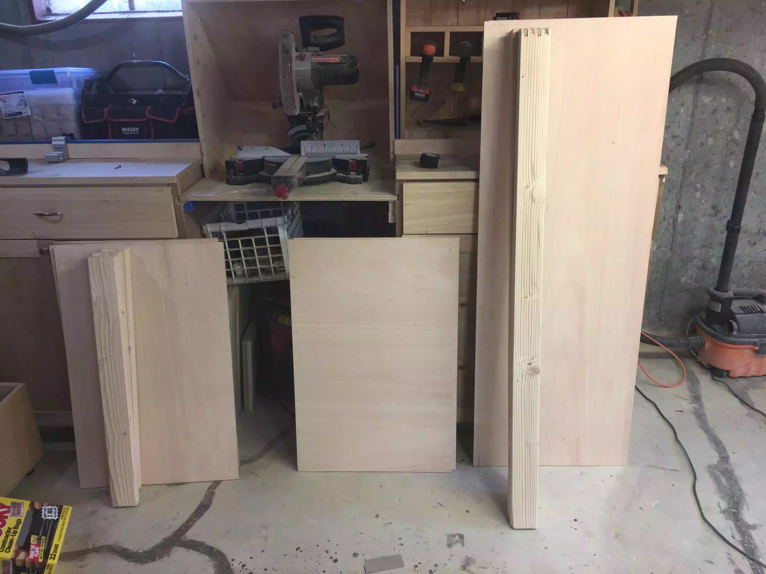
Using my plans I cut all plywood parts to size, I used a mix of birch plywood and regular sanded plywood for all the drawer parts (needed to get rid of some scrap plywood, that’s why I used the sanded plywood. With the exception of the drawer bases all materials were 23/32” thick, the drawer base was 1/2” thick I needed very robust bases as I will be putting heavy tools in them.
I used my table-saw to rip cut all the drawer parts and cross-cut most of the drawer parts on my chop saw with the exception of the drawer bases which I used my crosscut sled on the table-saw.

Drawer frame cut to size, since I am using 4 different heights of drawer that is why there is 4 lots of parts.

I was so happy that I left this final part of the build for last as I get to actually use my assembly table for its first project, its drawers. Its extremely handy having a longer work surface.

Here are the 8 drawer bases all cut to size.
JOINERY
I chose to use the same joinery method as “The Wood Whisperer” did in his build for the drawers and that is the rabbet joint, with a dado for the drawer base.
Basically cut a rabbet on the front and back drawer pieces which is where the drawer sides are captured and then I use glue and brad nails to secure all the parts together, the drawer base just sits into a dado that is 1/2” up from all 4 sides and I made it 1/4” deep.
This method is extremely quick and I banged out all 8 drawers in about 2 hours.

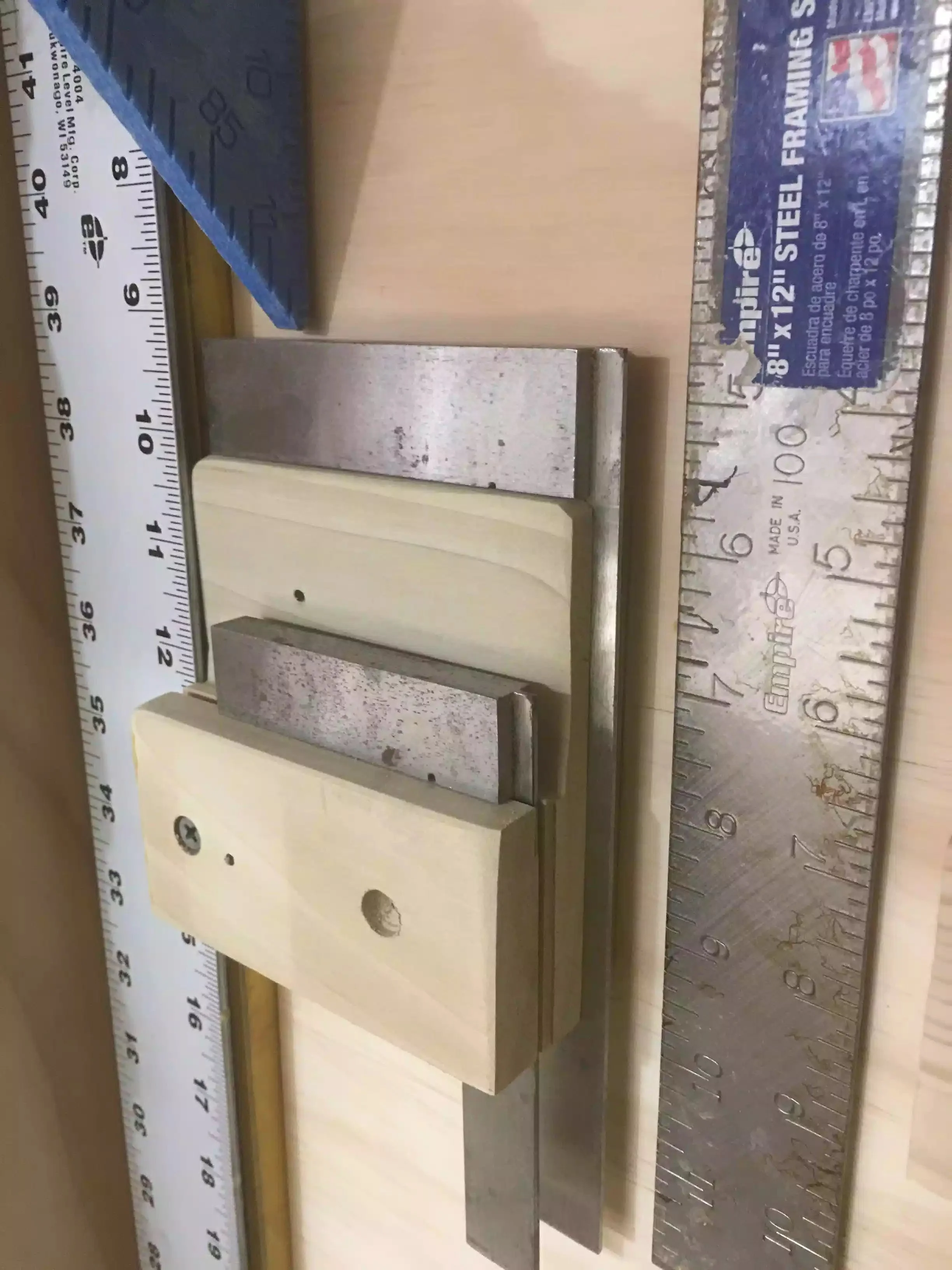
My first step was cut 2 rabbet’s on each side of the front and back drawer piece, its a 1/2” deep and 23/32” wide, I installed a sacrificial fence to my table-saw fence and then also installed a dado stack in my saw to get the job done. I only placed rabbets on the front & back pieces of all the drawers, the sides do not receive the joint.

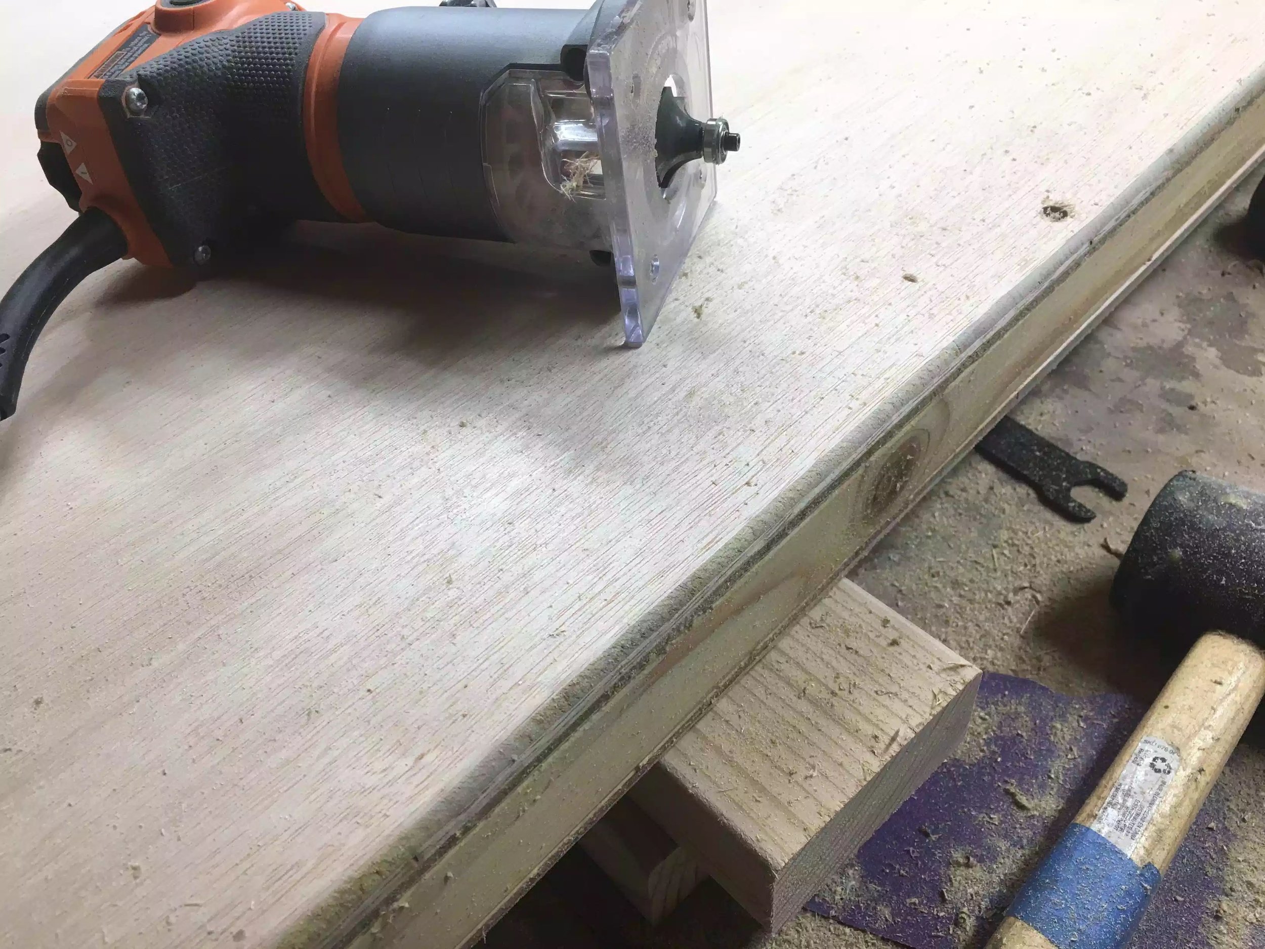
Here is a close up of the left side rabbet, that 1/4” front piece is what hides the joint on the front when it is all glue together, it also enables you to have more glue surface for a better bond on the drawer.

Here is what the drawer front& back pieces should look like.

My next step was cut the dado for the drawer bottoms on all drawer pieces, I placed the dado 1/2” up from the bottom and the dado is 1/2” wide and 1/4” deep, I also used my dado stack for this step.

Here is a close look at the dado which is where the drawer base will be housed, this panel will float in here so no glue will be needed during the glue-up phase.
A LITTLE SANDING
After all the joints are now cut in all the drawer pieces I sanded them with 120 grit sand paper using my random orbital sander. I usually only sand the inside faces of the drawer parts and then sand the outsides of the drawer once all the glue has dried.

DRY ASSEMBLY
Now that all the drawer parts are ready for the glue up I usually do a dry assembly to make sure that I rehearse the order in which I assemble the drawer, I also make sure that the drawers are square, which they were.

Here are the drawer parts al laid out for assembly, I place glue on the drawer back & front and then assemble the drawer and secure the corners with 1-1/4” brad nails.

Here is one of the assembled drawers

Here is a close-up of the rabbet joint on the front of the drawer

All 8 drawers are assembled and ready for installation
DRAWER INSTALLATION
Installation of the drawers was pretty quick and easy, I used 18” long side mounted drawer runners on all the cabinet drawers and I came up with a quick installation method for them, I made a quick jig for the drawer slides to help with alignment. The drawer runners I used had 2 parts to them, one part gets screwed to the case and he other gets screwed to the drawer there was a 1/2” overlay between the 2 parts so a made a offset jig that I could align the drawer part so as that they were uniform on every drawer.
STEP 1: I used a 1/4” spacer so as that I could sit my drawer slide on and keep an even reveal.

I used 1/4” thick piece of MDF as a spacer
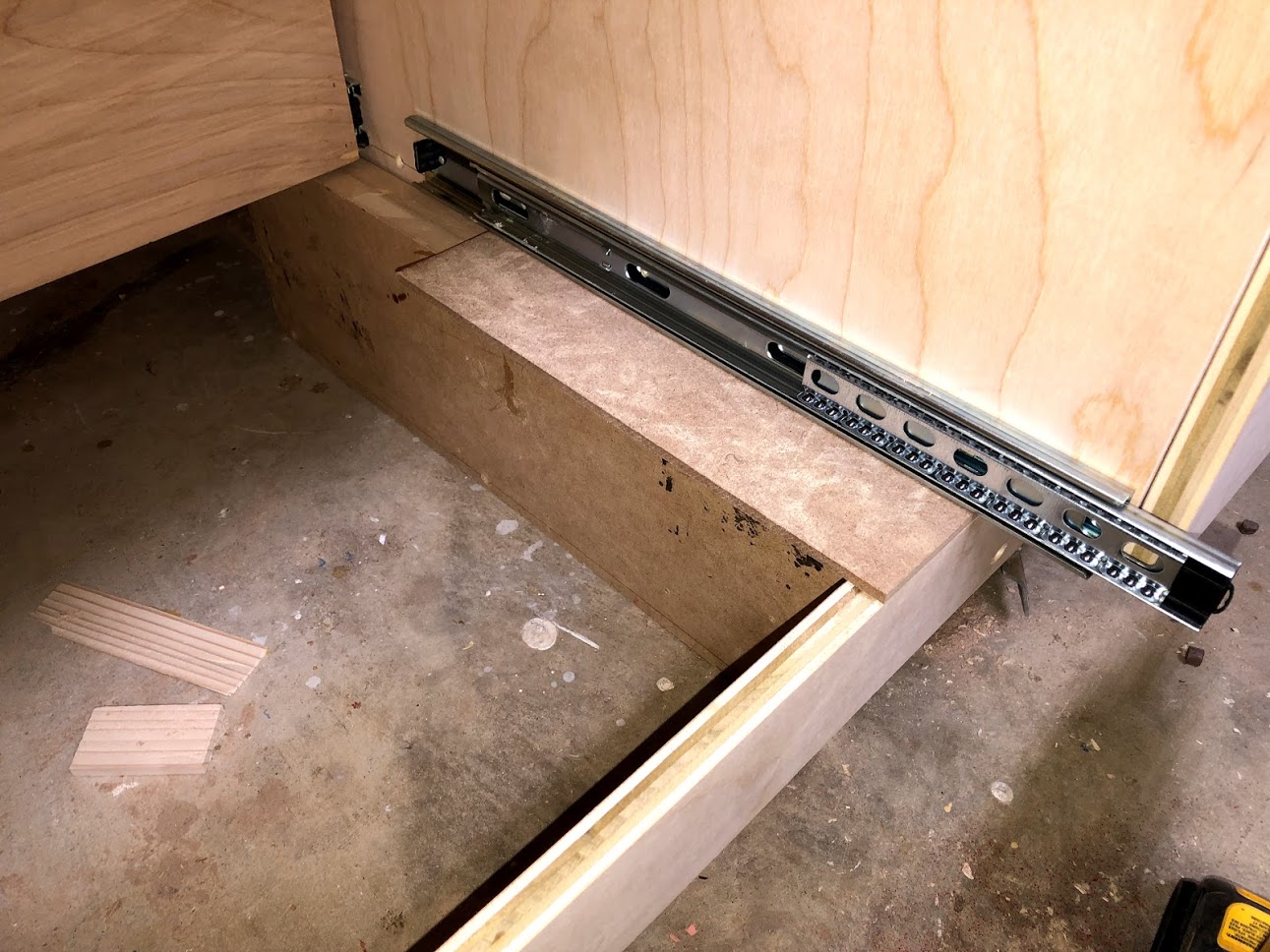
I lay the drawer slide on the 1/4’ thick piece of MDF and secured it to the cabinet case
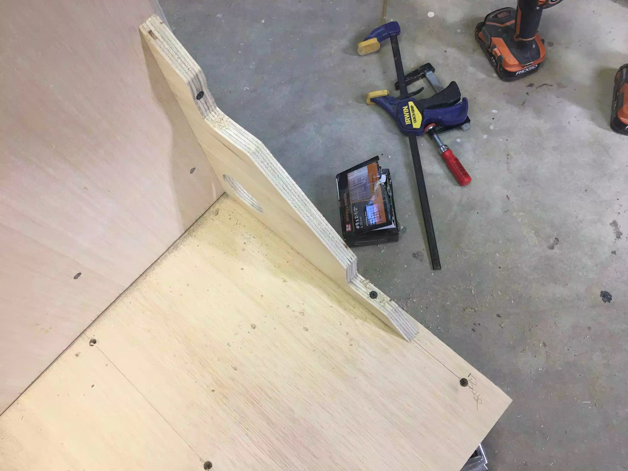
STEP 2: Used a shop made jig to align the drawer part of the slide

With the jig butted up to the base of the drawer I just lay the drawer slide next to it and screw it in place with 3 screws.

Here is a close up of the jig, its basically a scrap piece of plywood with a fence on the side that is 1-1/4” wide which when butted next to the 3/4” thick plywood gives me the required 1/2” offset to install the drawer slide.
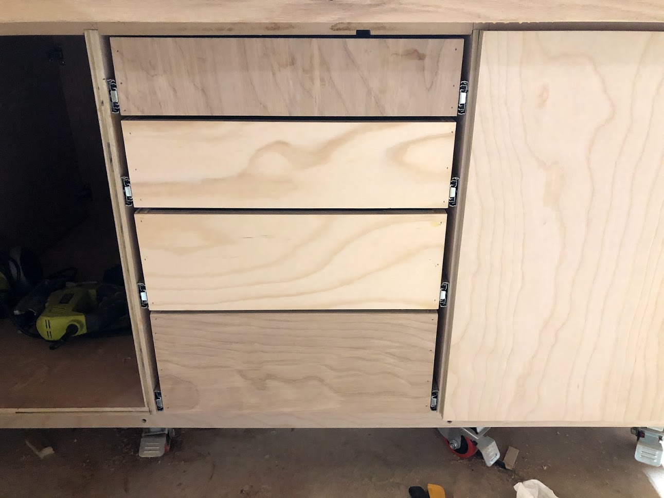
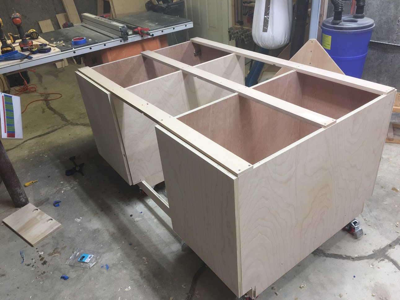
Here are all the 4 drawer box installed on one side, I repeated this on the other side of the assembly table.
DRAWER FALSE FRONTS
I made sure to use a single plywood panel for all my false fronts so as that I could cut them sequentially and maintain the grain pattern for all the fronts, I really think it adds that cohesive look to the bank of drawers. The installation of the false fronts was very easy.
Apply glue to the back of the false front
Secure in place on the drawer using 2 clamps
Drive a few brad nails from inside the drawer holding the false front in place
Finally secure with 1-1/4” screws from inside the drawer.

Applied glue to the back of the false front

Held the false front in place with clamps while I secured brad nails from inside the drawer, after that I secured permanently with screws

2 false front installed, as you can see the grain matches up as you look at the drawers.

Here is a picture of all the false fronts added on one side, I repeated this on the other side, it looks great, next up is attaching the handles.
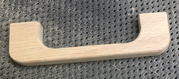
ATTACHING THE DRAWER PULLS
If you can remember I made my own solid oak drawer pulls a little while ago and it was time to install them on the drawers and doors.
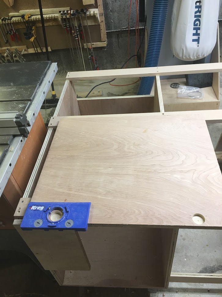
I purchased a Kreg jig some time ago while I was making my drill press cart and it was time to use it again, this is a great little jig if you install drawer pulls, and it works great every time.

With the center of the drawer marked I lined up my Jig and predrilled the 2 holes required to secure the drawer pulls.

Holes predrilled, all that was left was to secured the pulls with 2 screws from the inside of the drawer.

Here is the first drawer pull installed

Here are all the oak drawer pulls attached, still need to sand the pencils marks .

With all the drawers done I turned my attention to installing the pulls on the cabinet drawers.
CABINET TRAYS
The Wood Whisperer design had some shelves on the inside of the cabinet doors but I didn’t think that would work in my situation, so I came up with a plan deviation and that was install pull out trays , they are basically very shallow drawers and are installed as drawers because they operate on drawer slides.
They allow my to utilize all the empty space behind the cabinet doors but have easy access to all contents instead of reaching into deep shelves and having a hard time finding what you are looking for.
I installed 4 pull out trays behind the left cabinet door, and I will be storing anything from my power tools that are too big to fit inside the drawers, I will also be storing my wood finishes and glue.
I made them the same way that I made my drawers except they don’t have false front and are only 3” deep. They work great and have so many uses, I have used them in my kitchen on more than one occasion.

The trays are very shallow, but the design and joinery method used are the same as the big drawers we just installed.

Here is one of the trays installed, works like a charm.

Since the tray operate on drawer slides it allows me easy access to the back of the tray

I made a total of 4 trays and loaded them up with all my stuff.

The name of the game is access, these work great ad better than any shelf in my opinion.
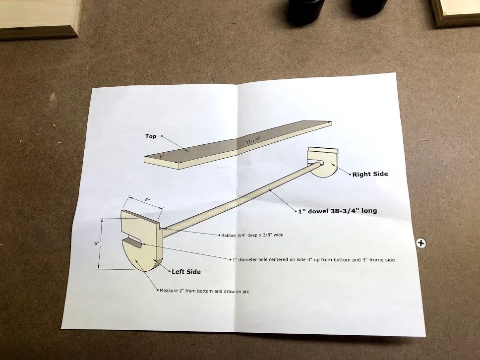
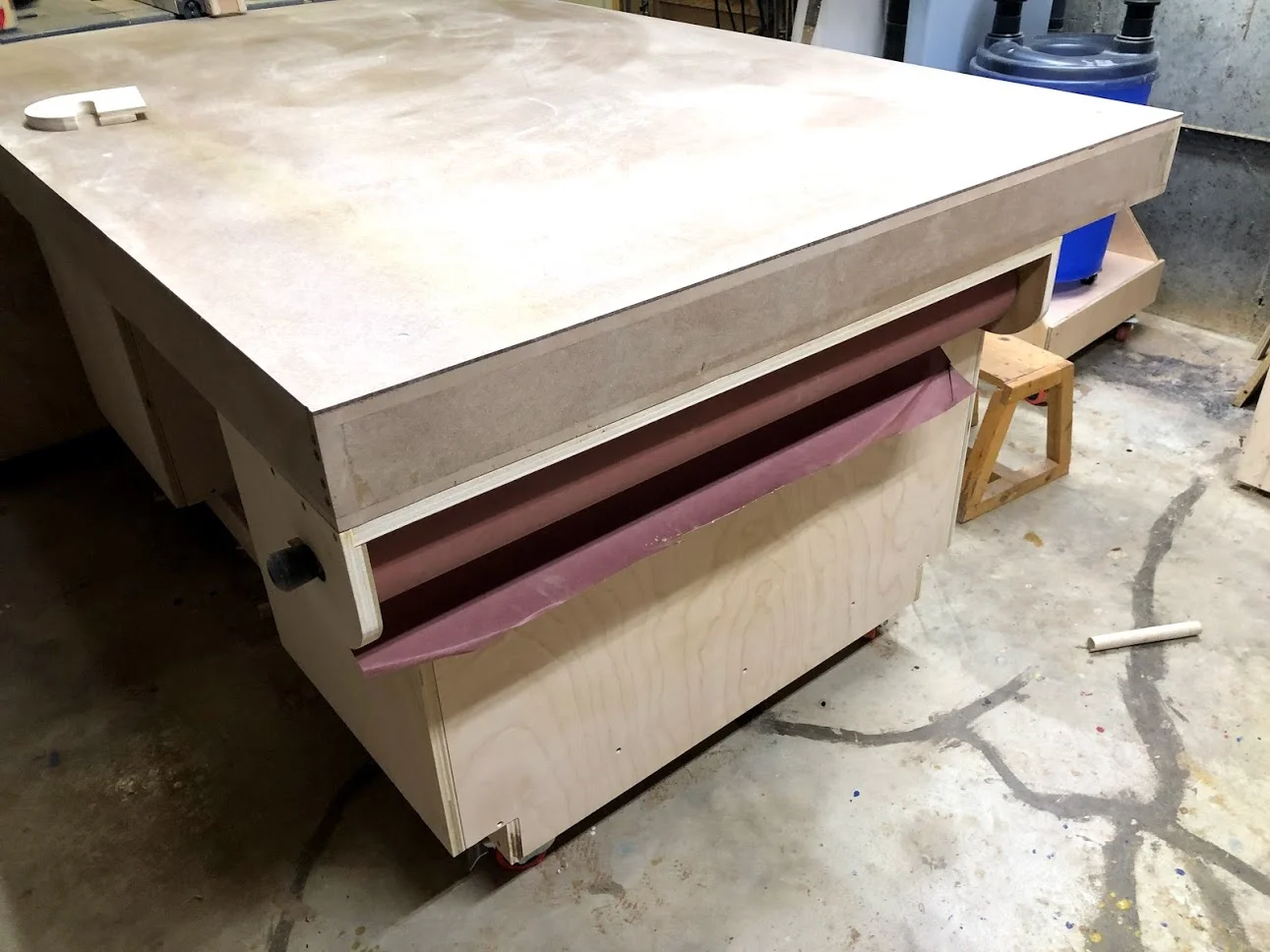
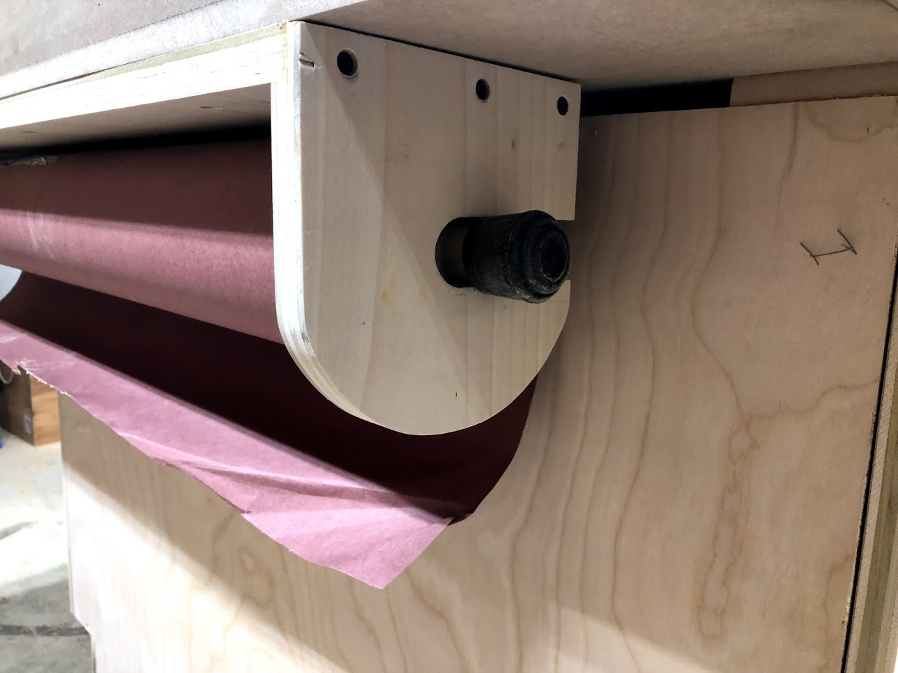
PAPER ROLL HOLDER
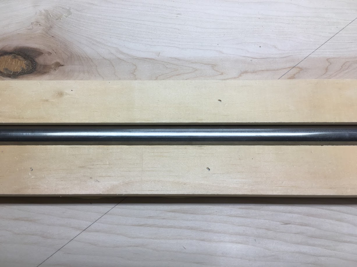
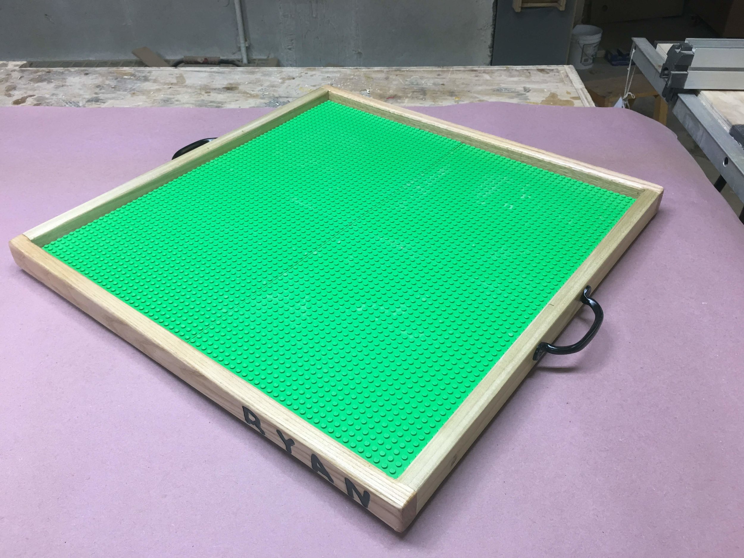
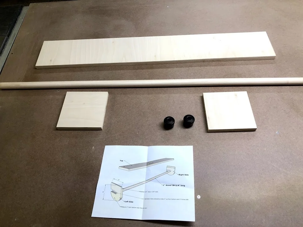
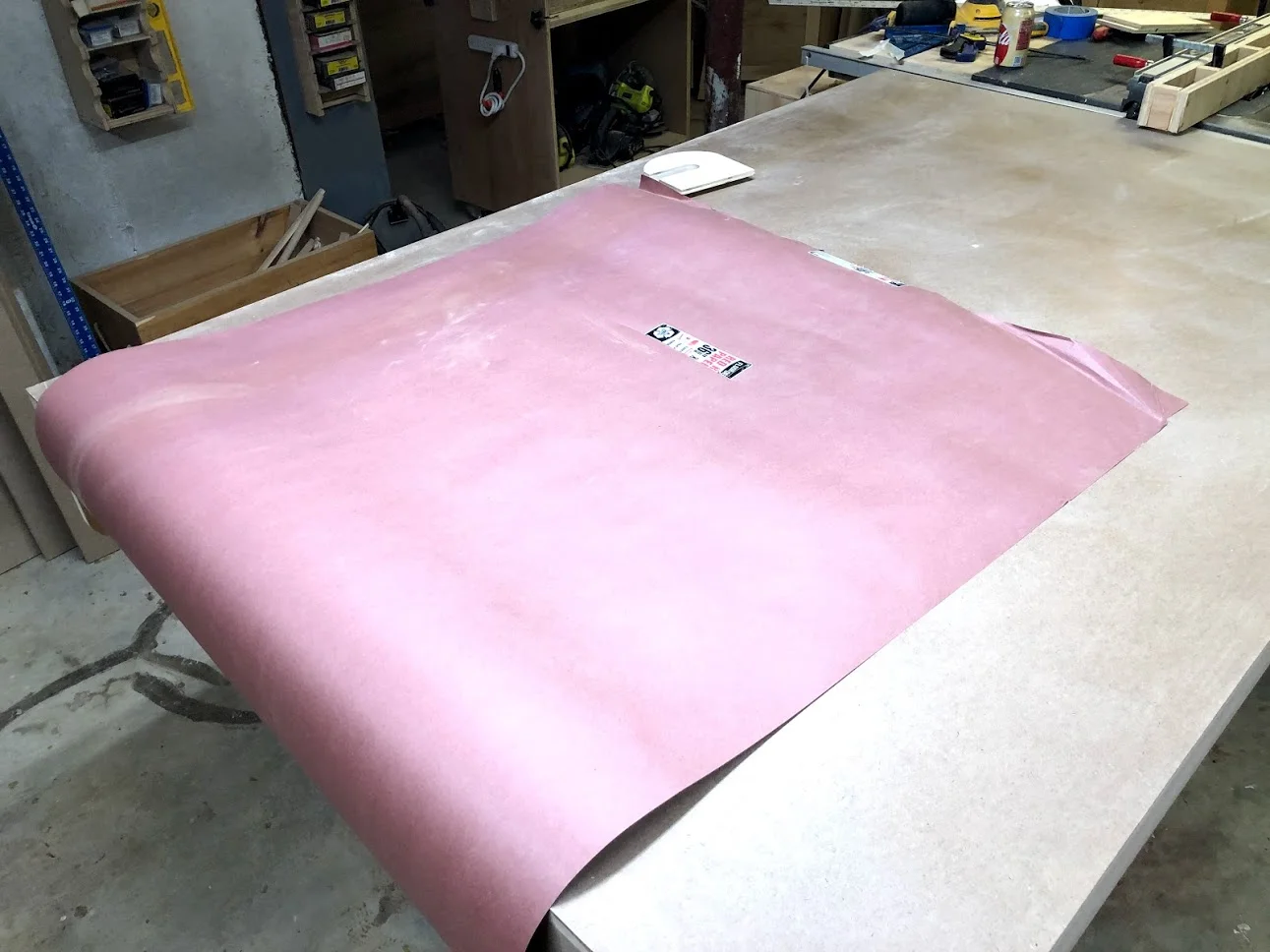
On my last outfeed assembly table I had made a home for my 36” long roll of resin paper, I used this to protect the top of the table when I was either gluing up a project or applying finishes.
I found this design on Jays Custom Creations, I will include a link below to his build video, although mine is very similar I didn’t use finger joints for the joinery method, I basically used glue and screws and rabbets to hold everything in place and it came out great.

Rosin paper all attached and works great, simple effective and cheap
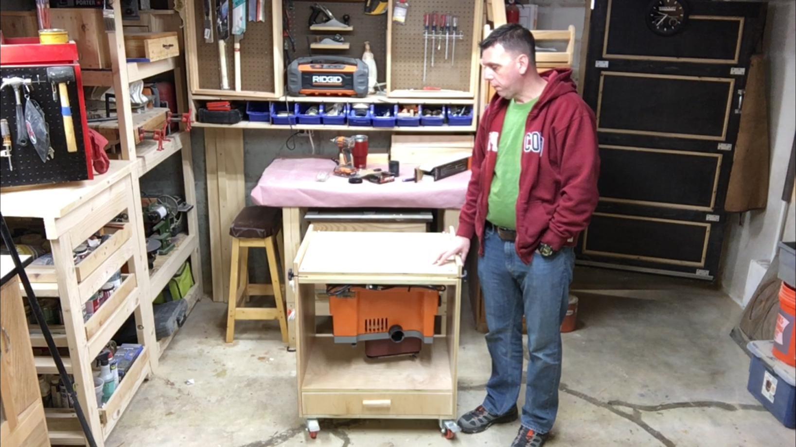
Phase III is all finished and we have a very functional assembly table with tons of storage with a variety of storage methods and a large assembly work surface.
My final stage of this huge build is to apply the finish and I will do that soon, this will probably take me a week to fully finish as it takes a while to apply polyurethane while sanding between coats, but when that is done I will post a finished article on the build.
See you next time and thanks for reading this long project blog, I really hope you got something out this project.