New Assembly Table

PHASE III : STORAGE

Phase III deals with the drawers, there will be 8 drawers in total which will be located on the 2 sides. The drawers increase size as you go down the cabinet starting at 4”, 5”, 6-1/2” and finally 8”.

Here is the steps I took in making them

  1. Cut all drawer parts to size.

  2. Joinery

  3. A little sanding

  4. Dry Assembly

  5. Drawer Glue Up: Assembly

  6. Drawer Installation

  7. False Fronts

  8. Drawer Pulls

  9. Cabinet Pull out Trays

  10. On board Paper Roll Holder

CUT PARTS TO SIZE

The most exciting part of this phase of the build is that I actually get to use the assembly table to build the drawers.

Using my plans I cut all plywood parts to size, I used a mix of birch plywood and regular sanded plywood for all the drawer parts (needed to get rid of some scrap plywood, that’s why I used the sanded plywood. With the exception of the drawer bases all materials were 23/32” thick, the drawer base was 1/2” thick I needed very robust bases as I will be putting heavy tools in them.

I used my table-saw to rip cut all the drawer parts and cross-cut most of the drawer parts on my chop saw with the exception of the drawer bases which I used my crosscut sled on the table-saw.

Drawer frame cut to size, since I am using 4 different heights of drawer that is why there is 4 lots of parts.

Drawer frame cut to size, since I am using 4 different heights of drawer that is why there is 4 lots of parts.

I was so happy that I left this final part of the build for last as I get to actually use my assembly table for its first project, its drawers. Its extremely handy having a longer work surface.

I was so happy that I left this final part of the build for last as I get to actually use my assembly table for its first project, its drawers. Its extremely handy having a longer work surface.

Here are the 8 drawer bases all cut to size.

Here are the 8 drawer bases all cut to size.

JOINERY

I chose to use the same joinery method as “The Wood Whisperer” did in his build for the drawers and that is the rabbet joint, with a dado for the drawer base.

Basically cut a rabbet on the front and back drawer pieces which is where the drawer sides are captured and then I use glue and brad nails to secure all the parts together, the drawer base just sits into a dado that is 1/2” up from all 4 sides and I made it 1/4” deep.

This method is extremely quick and I banged out all 8 drawers in about 2 hours.

My first step was cut 2 rabbet’s on each side of the front and back drawer piece, its a 1/2” deep and 23/32” wide, I installed a sacrificial fence to my table-saw fence and then also installed a dado stack in my saw to get the job done. I only place…

My first step was cut 2 rabbet’s on each side of the front and back drawer piece, its a 1/2” deep and 23/32” wide, I installed a sacrificial fence to my table-saw fence and then also installed a dado stack in my saw to get the job done. I only placed rabbets on the front & back pieces of all the drawers, the sides do not receive the joint.

Here is a close up of the left side rabbet, that 1/4” front piece is what hides the joint on the front when it is all glue together, it also enables you to have more glue surface for a better bond on the drawer.

Here is a close up of the left side rabbet, that 1/4” front piece is what hides the joint on the front when it is all glue together, it also enables you to have more glue surface for a better bond on the drawer.

Here is what the drawer front& back pieces should look like.

Here is what the drawer front& back pieces should look like.

My next step was cut the dado for the drawer bottoms on all drawer pieces, I placed the dado 1/2” up from the bottom and the dado is 1/2” wide and 1/4” deep, I also used my dado stack for this step.

My next step was cut the dado for the drawer bottoms on all drawer pieces, I placed the dado 1/2” up from the bottom and the dado is 1/2” wide and 1/4” deep, I also used my dado stack for this step.

Here is a close look at the dado which is where the drawer base will be housed, this panel will float in here so no glue will be needed during the glue-up phase.

Here is a close look at the dado which is where the drawer base will be housed, this panel will float in here so no glue will be needed during the glue-up phase.


A LITTLE SANDING

After all the joints are now cut in all the drawer pieces I sanded them with 120 grit sand paper using my random orbital sander. I usually only sand the inside faces of the drawer parts and then sand the outsides of the drawer once all the glue has dried.

blob

DRY ASSEMBLY

Now that all the drawer parts are ready for the glue up I usually do a dry assembly to make sure that I rehearse the order in which I assemble the drawer, I also make sure that the drawers are square, which they were.

Here are the drawer parts al laid out for assembly, I place glue on the drawer back & front and then assemble the drawer and secure the corners with 1-1/4” brad nails.

Here are the drawer parts al laid out for assembly, I place glue on the drawer back & front and then assemble the drawer and secure the corners with 1-1/4” brad nails.

Here is one of the assembled drawers

Here is one of the assembled drawers

Here is a close-up of the rabbet joint on the front of the drawer

Here is a close-up of the rabbet joint on the front of the drawer

All 8 drawers are assembled and ready for installation

All 8 drawers are assembled and ready for installation


DRAWER INSTALLATION

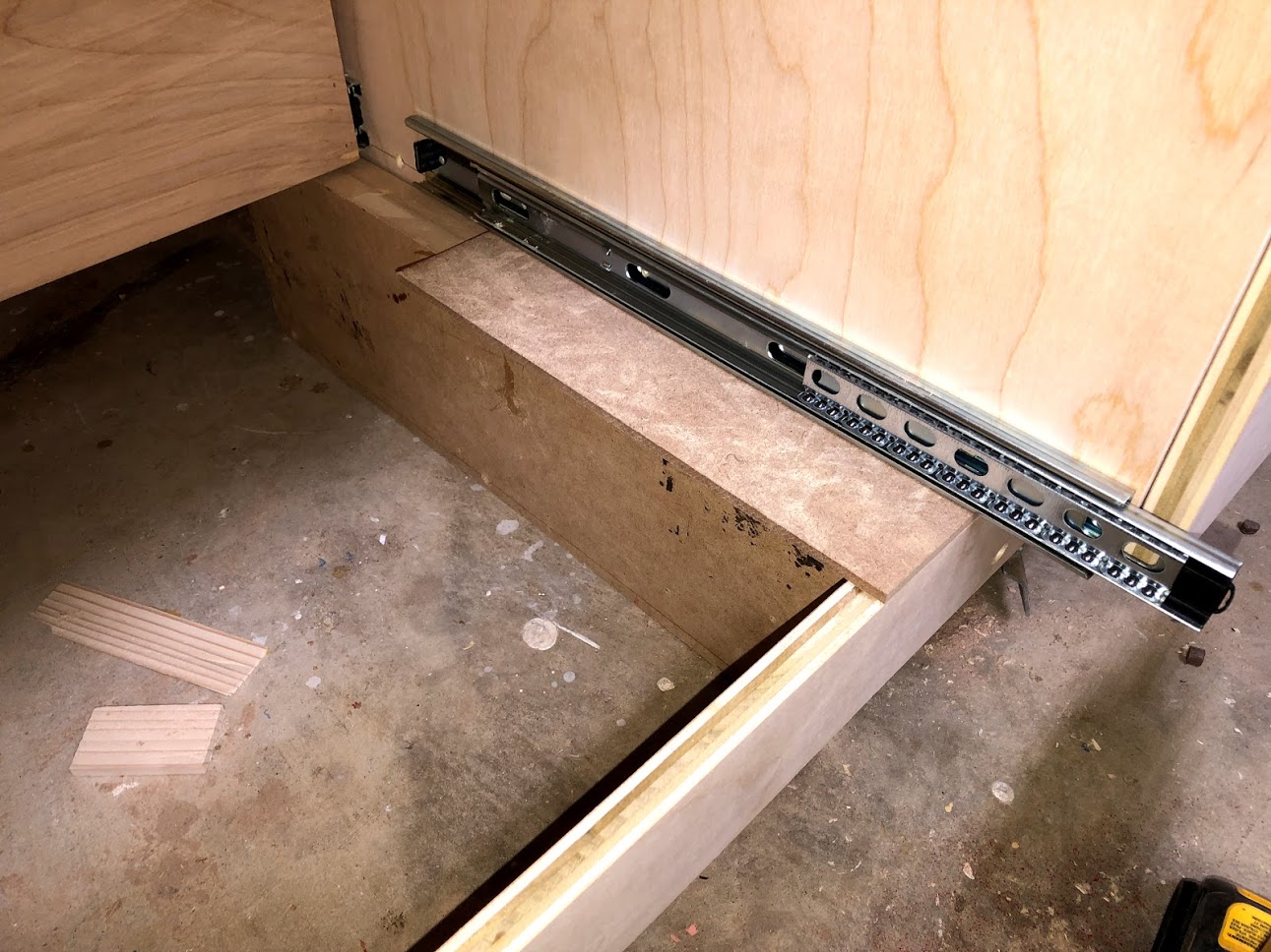
Installation of the drawers was pretty quick and easy, I used 18” long side mounted drawer runners on all the cabinet drawers and I came up with a quick installation method for them, I made a quick jig for the drawer slides to help with alignment. The drawer runners I used had 2 parts to them, one part gets screwed to the case and he other gets screwed to the drawer there was a 1/2” overlay between the 2 parts so a made a offset jig that I could align the drawer part so as that they were uniform on every drawer.

STEP 1: I used a 1/4” spacer so as that I could sit my drawer slide on and keep an even reveal.

I used 1/4” thick piece of MDF as a spacer

I used 1/4” thick piece of MDF as a spacer

I lay the drawer slide on the 1/4’ thick piece of MDF and secured it to the cabinet case

I lay the drawer slide on the 1/4’ thick piece of MDF and secured it to the cabinet case

STEP 2: Used a shop made jig to align the drawer part of the slide

With the jig butted up to the base of the drawer I just lay the drawer slide next to it and screw it in place with 3 screws.

With the jig butted up to the base of the drawer I just lay the drawer slide next to it and screw it in place with 3 screws.

Here is a close up of the jig, its basically a scrap piece of plywood with a fence on the side that is 1-1/4” wide which when butted next to the 3/4” thick plywood gives me the required 1/2” offset to install the drawer slide.

Here is a close up of the jig, its basically a scrap piece of plywood with a fence on the side that is 1-1/4” wide which when butted next to the 3/4” thick plywood gives me the required 1/2” offset to install the drawer slide.

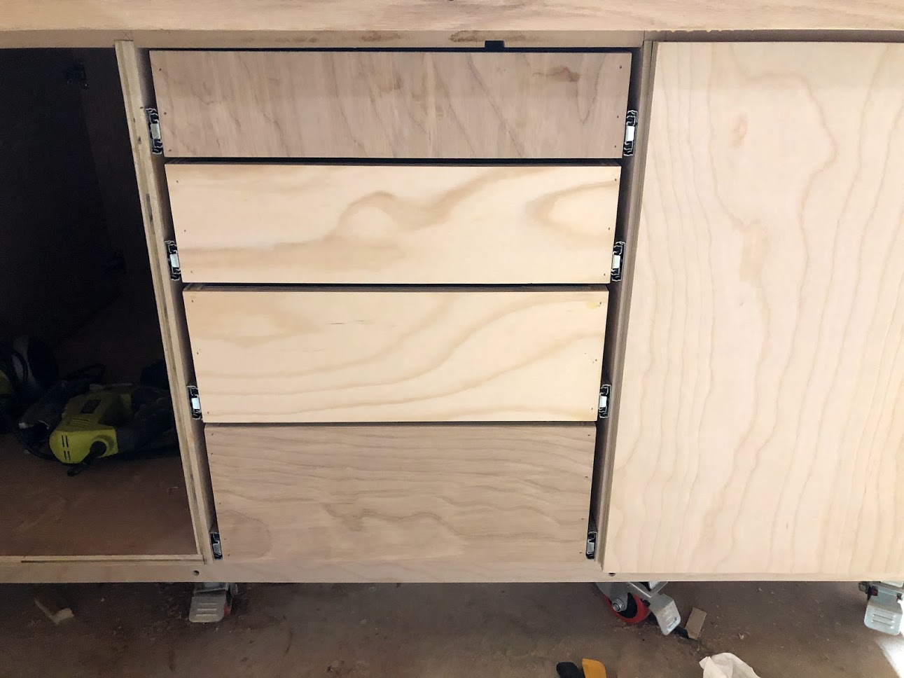
Here are all the 4 drawer box installed on one side, I repeated this on the other side of the assembly table.

Here are all the 4 drawer box installed on one side, I repeated this on the other side of the assembly table.


DRAWER FALSE FRONTS

I made sure to use a single plywood panel for all my false fronts so as that I could cut them sequentially and maintain the grain pattern for all the fronts, I really think it adds that cohesive look to the bank of drawers. The installation of the false fronts was very easy.

  • Apply glue to the back of the false front

  • Secure in place on the drawer using 2 clamps

  • Drive a few brad nails from inside the drawer holding the false front in place

  • Finally secure with 1-1/4” screws from inside the drawer.

Applied glue to the back of the false front

Applied glue to the back of the false front

Held the false front in place with clamps while I secured brad nails from inside the drawer, after that I secured permanently with screws

Held the false front in place with clamps while I secured brad nails from inside the drawer, after that I secured permanently with screws

2 false front installed, as you can see the grain matches up as you look at the drawers.

2 false front installed, as you can see the grain matches up as you look at the drawers.

Here is a picture of all the false fronts added on one side, I repeated this on the other side, it looks great, next up is attaching the handles.

Here is a picture of all the false fronts added on one side, I repeated this on the other side, it looks great, next up is attaching the handles.


ATTACHING THE DRAWER PULLS

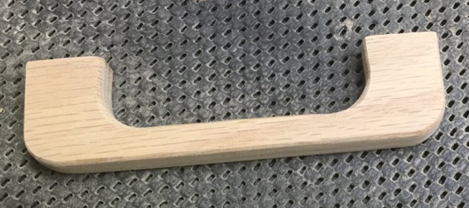
If you can remember I made my own solid oak drawer pulls a little while ago and it was time to install them on the drawers and doors.

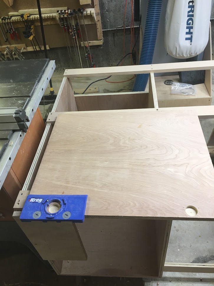
I purchased a Kreg jig some time ago while I was making my drill press cart and it was time to use it again, this is a great little jig if you install drawer pulls, and it works great every time.

With the center of the drawer marked I lined up my Jig and predrilled the 2 holes required to secure the drawer pulls.

With the center of the drawer marked I lined up my Jig and predrilled the 2 holes required to secure the drawer pulls.

Holes predrilled, all that was left was to secured the pulls with 2 screws from the inside of the drawer.

Holes predrilled, all that was left was to secured the pulls with 2 screws from the inside of the drawer.

Here is the first drawer pull installed

Here is the first drawer pull installed

Here are all the oak drawer pulls attached, still need to sand the pencils marks .

Here are all the oak drawer pulls attached, still need to sand the pencils marks .

With all the drawers done I turned my attention to installing the pulls on the cabinet drawers.

With all the drawers done I turned my attention to installing the pulls on the cabinet drawers.


CABINET TRAYS

The Wood Whisperer design had some shelves on the inside of the cabinet doors but I didn’t think that would work in my situation, so I came up with a plan deviation and that was install pull out trays , they are basically very shallow drawers and are installed as drawers because they operate on drawer slides.

They allow my to utilize all the empty space behind the cabinet doors but have easy access to all contents instead of reaching into deep shelves and having a hard time finding what you are looking for.

I installed 4 pull out trays behind the left cabinet door, and I will be storing anything from my power tools that are too big to fit inside the drawers, I will also be storing my wood finishes and glue.

I made them the same way that I made my drawers except they don’t have false front and are only 3” deep. They work great and have so many uses, I have used them in my kitchen on more than one occasion.

The trays are very shallow, but the design and joinery method used are the same as the big drawers we just installed.

The trays are very shallow, but the design and joinery method used are the same as the big drawers we just installed.

Here is one of the trays installed, works like a charm.

Here is one of the trays installed, works like a charm.

Since the tray operate on drawer slides it allows me easy access to the back of the tray

Since the tray operate on drawer slides it allows me easy access to the back of the tray

I made a total of 4 trays and loaded them up with all my stuff.

I made a total of 4 trays and loaded them up with all my stuff.

The name of the game is access, these work great ad better than any shelf in my opinion.

The name of the game is access, these work great ad better than any shelf in my opinion.


PAPER ROLL HOLDER

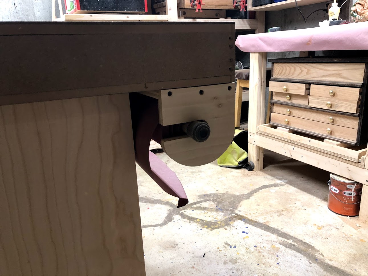
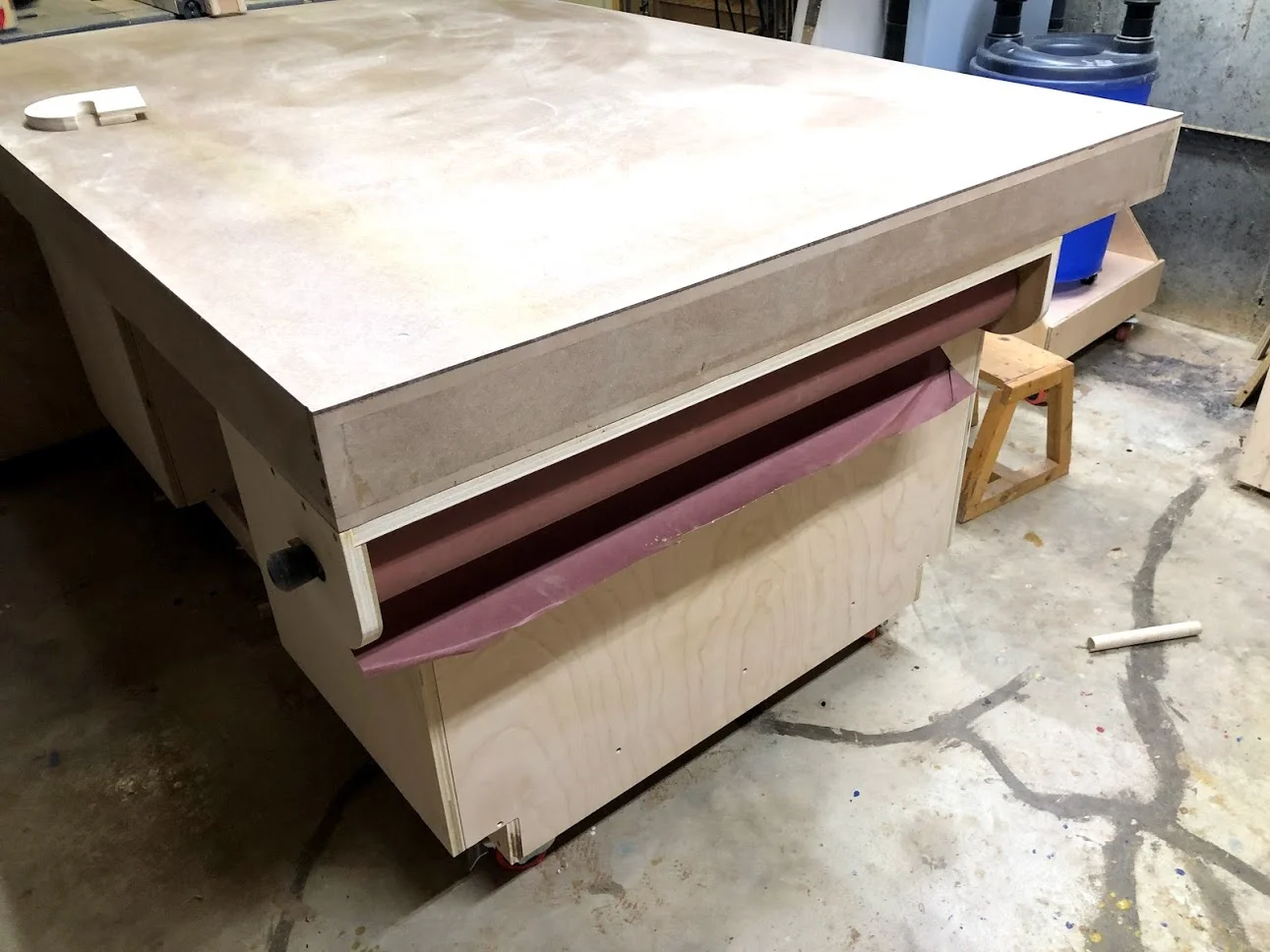
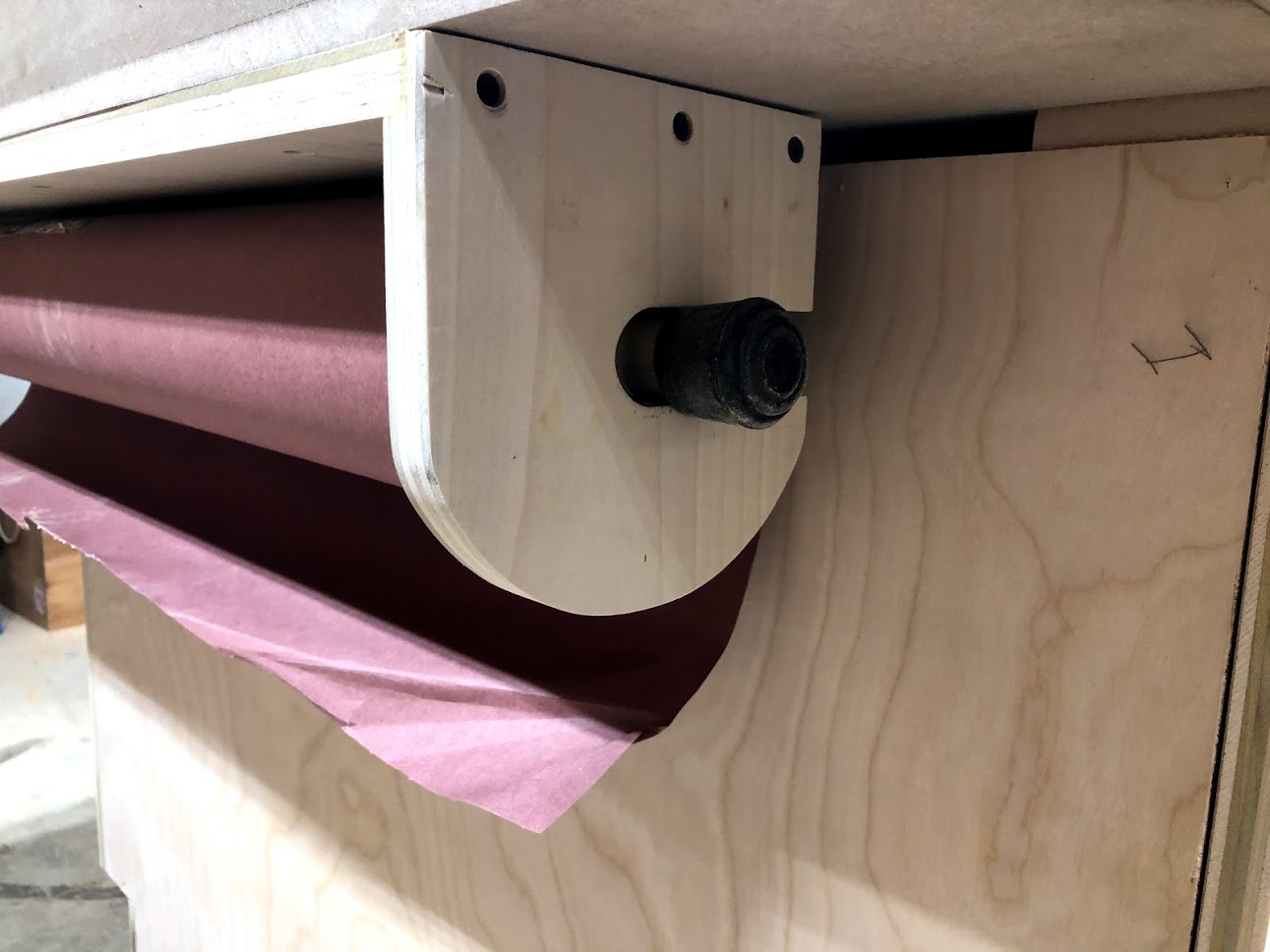
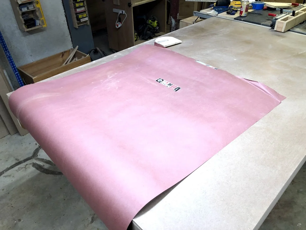
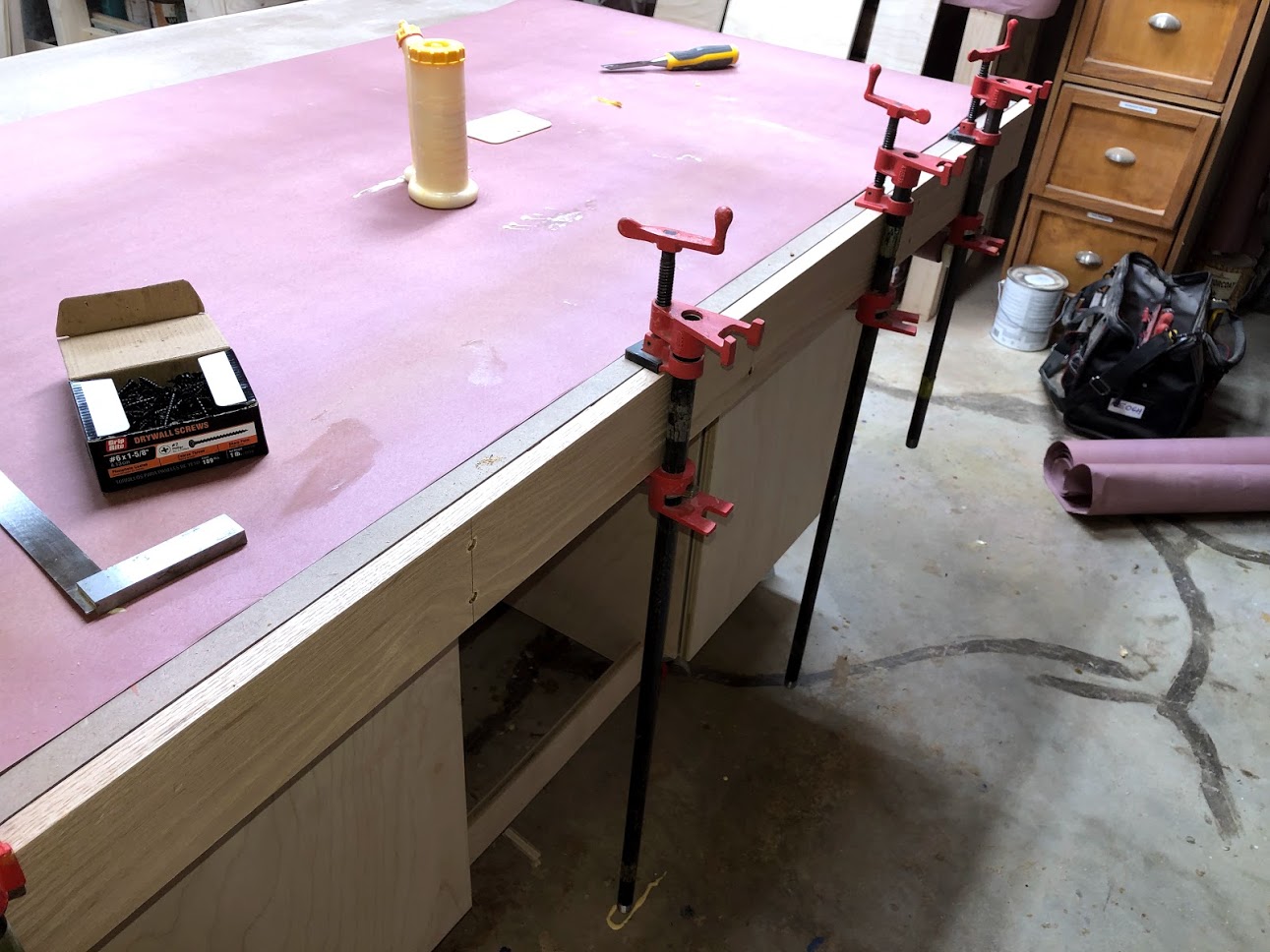
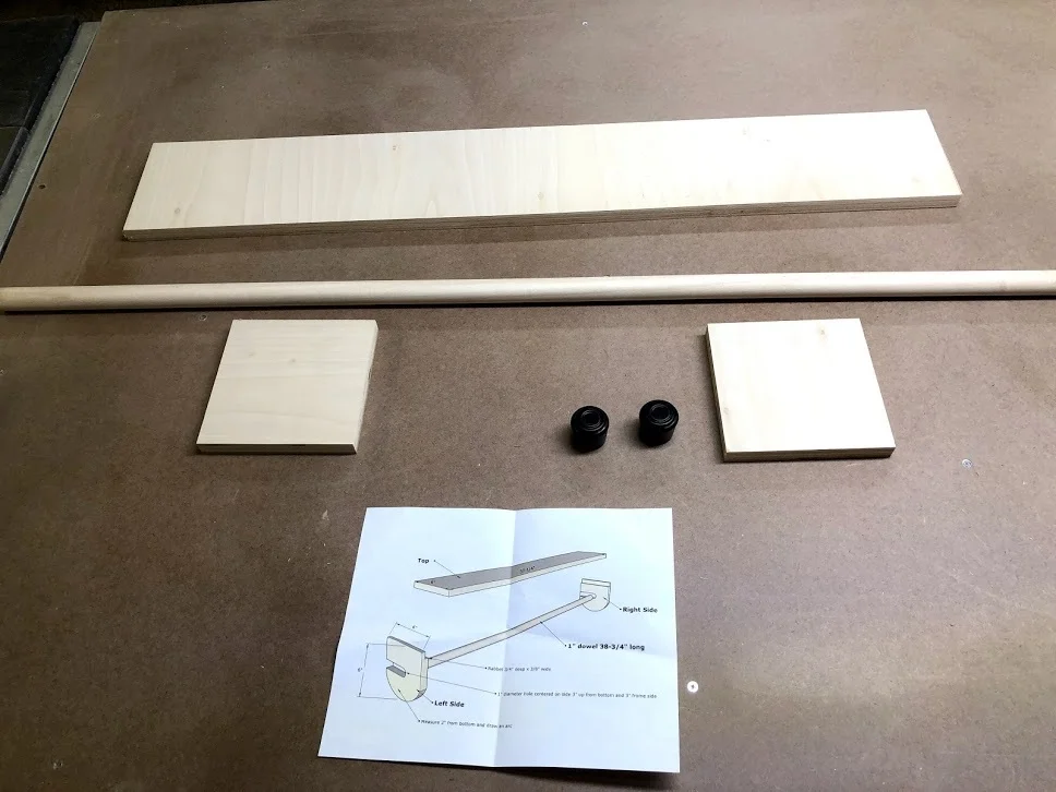
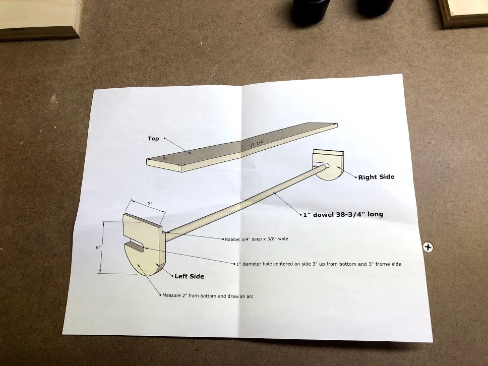
On my last outfeed assembly table I had made a home for my 36” long roll of resin paper, I used this to protect the top of the table when I was either gluing up a project or applying finishes.

I found this design on Jays Custom Creations, I will include a link below to his build video, although mine is very similar I didn’t use finger joints for the joinery method, I basically used glue and screws and rabbets to hold everything in place and it came out great.

Rosin paper all attached and works great, simple effective and cheap
Rosin paper all attached and works great, simple effective and cheap
Phase III is all finished and we have a very functional assembly table with tons of storage with a variety of storage methods and a large assembly work surface.

My final stage of this huge build is to apply the finish and I will do that soon, this will probably take me a week to fully finish as it takes a while to apply polyurethane while sanding between coats, but when that is done I will post a finished article on the build.

See you next time and thanks for reading this long project blog, I really hope you got something out this project.

Phase II: THE TORSION BOX TOP (AMENDED)

Here is a layered view of the torsion box

Here is a layered view of the torsion box

Phase 2 of the project deals exclusively with the Torsion box top that will be installed on top of the cabinet base that we made in Phase 1. 

A torsion box top is extremely functional in that it’s basically a shallow box with a grid work inside that provides a very flat stable surface to work on. 

The torsion box is made with the following materials:

  • (2) 1/2” thick MDF panels for top and bottom skins

  • (2) 3/4”  thick x 3” high outer frame long pieces

  • (2) 3/4”  thick x 3” high outer short pieces

  • (1) hardboard sheet (which will make up the replaceable top

HERE ARE THE STEPS

  • Built some saw horses

  • Staging area

  • A little Prep

  • Assembled the torsion box frame

  • Installed the torsion grid pieces

  • Added the skins

  • Added the hardwood trim (just added)

MADE SOME SAW HORSES

In order for me to assemble the torsion box I needed to take down my old outfeed table so as that I had some room to work, but you needed an assembly table to make an assembly table.

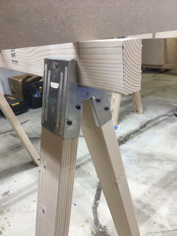
So I went to my big box store and got a couple lengths of 2x4’s and I also got some metal saw horse brackets that were really cheap and quick to make into saw horses.

It took about 15 minutes to make these, not bad.

It took about 15 minutes to make these, not bad.

STAGING AREA

So now that my saw horses are made, its time to make my makeshift staging area so as that I can start to assemble the top. Below you can see that I added 4 long work supports this was done to make sure that the MDF sheet that I will be put on this is dead flat, there was no point going through all the trouble of shimming the saw horse legs and make them level If they top that the mdf skin was sitting on wasn’t level.

IMG_4422.JPG
Everything nice and level

Everything nice and level

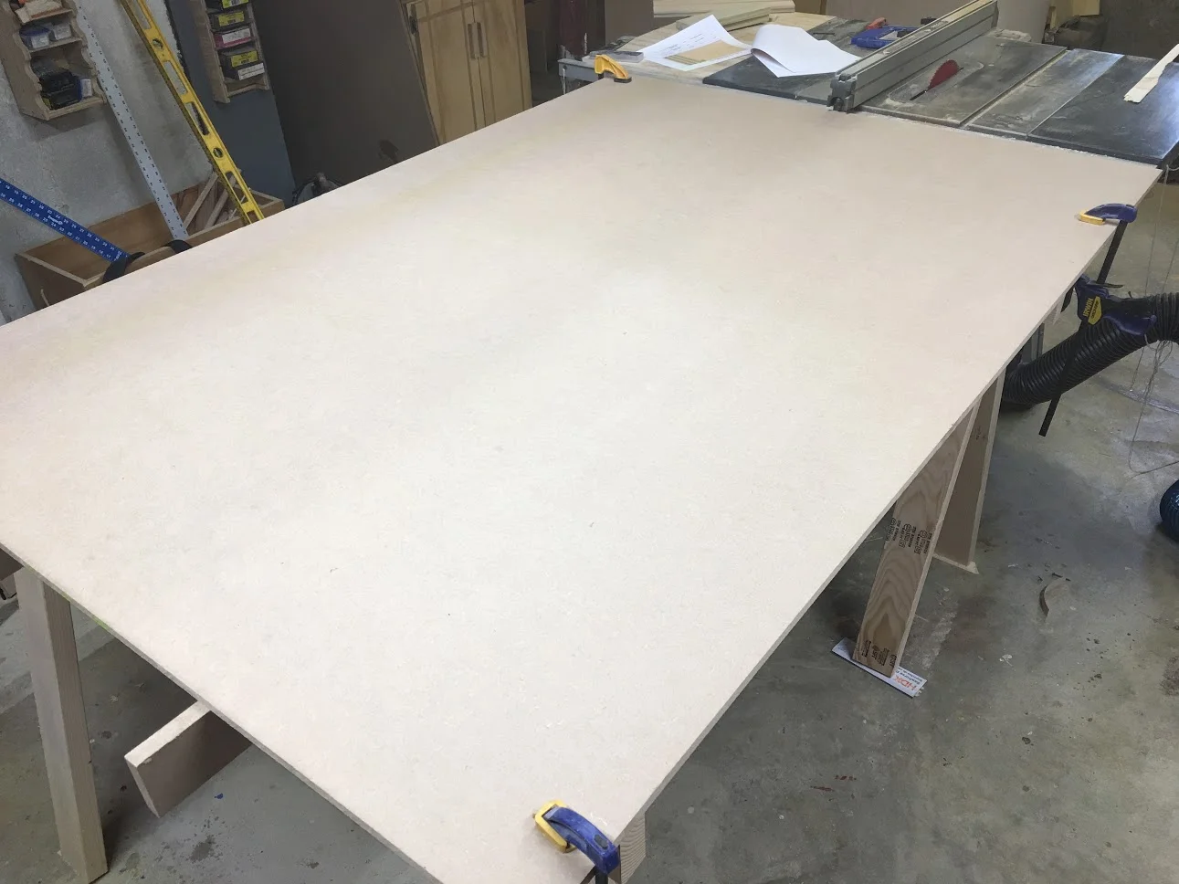
This is the MDF skin that I through up onto the saw horses, this will be one of the surfaces of the torsion box, but for right now it is my temporary assemble table.

This is the MDF skin that I through up onto the saw horses, this will be one of the surfaces of the torsion box, but for right now it is my temporary assemble table.

A LITTLE PREP

Before I get started making the outer torsion box frame I applied a coating of paste wax to the MDF panel that I will be making the torsion box on so as that glue will not stick to it as this will eventually be the top surface of my top.

IMG_0006.jpg

TORSION BOX BEGINNING

I broke PHASE II :- Torsion Box Top into the following sections

  • Torsion Box Frame

  • Torsion Box Grid

  • The Skins

  • The Replaceable Hardboard Top

  • Solid Wood Trim

THE FRAME

To describe the frame I am referring to the pieces that go around the torsion box grid, as show in the image below, the grey pieces represent the torsion box frame, these pieces wrap the torsion box grid pieces and later in the process I will attaching solid wood trim to them.

These pieces are cut to 2 lengths

  • Two long pieces for the sides

  • Two short pieces for the top and bottom of the torsion box.

TB frame.jpg
Here is an image of the frame pieces

Here is an image of the frame pieces

I used glue and screws to secure the long frame pieces into the shorter ones.

I used glue and screws to secure the long frame pieces into the shorter ones.

THE GRID

The grid was the most time consuming part of the torsion box top, mainly because of the number of parts that needed to be cut, glued and brad nailed into position.

The grid consisted off: 45 short grid pieces and 8 longer pieces. There were 9 rows of small grid pieces that measured 7-1/4” wide. My process was simple enough but took a while to complete.

I used a spacer strip to line up all the small grid pieces to try and keep everything aligned but that was not really absolutely necessary your goal is to make it flat and it doesn’t really matter how the grid looked because once the skins go on the grid will never see the light of day again, but it must be flat or it defeats the whole purpose of the torsion box

In the diagram below you can see the long grid pieces (blue) and short grid pieces (magenta)

inner grid 3.2.jpg
Here is an image of the grid completed.

Here is an image of the grid completed.

I used clamps to keep the mdf panel flat as I was conforming the inner grid to that surface, it does not have to look pretty but it needs to be flat

I used clamps to keep the mdf panel flat as I was conforming the inner grid to that surface, it does not have to look pretty but it needs to be flat

Here is a close up of the grid

Here is a close up of the grid

THE SKINS

The skins are what make up the top and bottom surfaces of the toson box, I used 1/2” thick MDF pieces as they are one of the most flat panels you can purchase and they stay flat as well.

Here are the steps I took to install the skins

  1. Applied glue to the tops of the grid pieces that were completed in the last step.

  2. Laid one of the MDF skins on top

  3. Marked out by drawing lines with a long ruler where the long grid pieces were located so as that I could attach the skin into these pieces, almost like clamps until the glue dried.

  4. After the glue had dried after a couple of hours I flipped the torsion box over and added the other skin in the same manner.

  5. I left the skins a little oversize so I came back with my router and flush cut router bit and made the skins flush with the outer frame.

Added glue on top of grid pieces.

Added glue on top of grid pieces.

Using my drywall framing ruler I draw visible lines to show here my grid pieces were located, that way I could anchor the top with brad nails .

Using my drywall framing ruler I draw visible lines to show here my grid pieces were located, that way I could anchor the top with brad nails .

Getting ready to nail the skin in place

Getting ready to nail the skin in place

After the skin is installed I also added a few screws and then using my router I flush trimmed the top making sure that all edges lines up.. I will be attaching my solid wood trim to the outside of the torsion box by the end of the project.

After the skin is installed I also added a few screws and then using my router I flush trimmed the top making sure that all edges lines up.. I will be attaching my solid wood trim to the outside of the torsion box by the end of the project.


THE REPLACEABLE HARDBOARD TOP

Now that the torsion box is built it was time to install the hardboard cover, this is only getting screwed into the skin no nails or glue was used because as time goes by the top will be beaten up and I will want to replace it.

Hardboard top installed, just needed to flush trim it and the box is almost finished, I need to go to my lumber supplier and get some red oak for the outside edges of the torsion box.

Hardboard top installed, just needed to flush trim it and the box is almost finished, I need to go to my lumber supplier and get some red oak for the outside edges of the torsion box.

With the torsion box completed it was time to marry the torsion box with the base cabinets, it was very easily done but help from a friend will be needed as the torsion box is not light.

I moved the torsion box from the saw horses and attached it to the cabinets using screws from the underside of the stretchers that we added in phase one.
Torsion Box attached to the cabinets.

Torsion Box attached to the cabinets.

A close up of the cabinet base, the oak will look awesome on the top once I get it, there isn’t any hurry.

A close up of the cabinet base, the oak will look awesome on the top once I get it, there isn’t any hurry.

ADDED THE SOLID OAK TRIM

I just completed this today and figured I would just add it to my original phase II post … here are the steps I took to completing this final build phase of the torsion box

  1. Cut my solid oak parts to its final dimensions

  2. Layout & Drilling holes

  3. Securing the trim

  4. Time for some dowels

  5. Router Time

  6. Sanding

PARTS

I needed 4 pieces of solid oak, two long pieces for the sides and 2 shorter pieces for the ends. I purchased a total of 20 feet of 1x6 solid oak and ripped it down to its final sizes.

Here are the 4 pieces of oak

Here are the 4 pieces of oak

A LITTLE LAYOUT

I decided to do a little layout to keep all the screw holes in the same location as yo went around the table, so I used my measuring tape to position the holes and my combination square to mark the center points for the holes. Then just used m drill with a countersinking bit to drill the holes.

Phase 2 is a wrap next up is Phase 3 which will be making the drawers for the cabinet base. I really hope you are enjoying this lengthy project but we are in the home stretch.

Here you can see the lines that I drew to locate where the holes where to go, they are in the same distance apart on all sides.

Here you can see the lines that I drew to locate where the holes where to go, they are in the same distance apart on all sides.

SECURING THE TRIM

Now that all my holes were drilled I needed to secure the trim , I used a trick that The Wood Whisperer used when installing the trim when you are along and that was to add clamps to the torsion box so as that the trim can balance on the clamps when you need to screw the trim place and it worked great, I also added glue to the back sides of the trim and the torsion box sides.

Here you can see the trim balancing on the clamps, just need to add screws.

Here you can see the trim balancing on the clamps, just need to add screws.

ADDED DOWELS

I wanted to use a contrasting wood for the dowel plugs so I picked up some walnut dowel rods and chopped them up into little 1/2” plugs. My process for this was very straightforward and I really love how they come out.

  • I cut the 36” long dowel rod into little plugs

  • Added glue to the counter-sunk holes and tapped in a dowel, I left the dowel proud so as that I could trim them flush after the glue dried.

  • Flush trimmed all the dowels and sanded flush

Dowels are flush cut and sanded smooth and really like the look.

Dowels are flush cut and sanded smooth and really like the look.

Here is the walnut dowel left proud, just waiting for the glue to dry.

Here is the walnut dowel left proud, just waiting for the glue to dry.

I trimmed the excess dowel, but still proud. Need to and them next

I trimmed the excess dowel, but still proud. Need to and them next

Dowels all finished.. look great

Dowels all finished.. look great

ROUTER TIME

I decided to also add a router profile to the trim so as that to remove any sharp edges from the oak, I decided to use chamfer profile bit in my handheld router to this. Really glad that I went with this profile as it also adds a nice characteristic to the trim, I could have used a round-over bit but I thought that would be a little boring.

Finally here is the finished Torsion box with solid oak trim.

Finally here is the finished Torsion box with solid oak trim.

Here is the chamfer bit I used on the slid oak trim

Here is the chamfer bit I used on the slid oak trim

Here you can see the chamfered edges, I did this to all outside edges of the oak trim.

Here you can see the chamfered edges, I did this to all outside edges of the oak trim.

All that was left was to sand the trim and break the other edges of the oak trim with 120 grit sandpaper and I called it a day.

I have to say that I really love this torsion box and glad I spent the little extra in choosing solid oak for the trim , the walnut plugs also add a nice look to the top.

NEXT:


Phase III : The drawers

Torsion Box Assembly Table : Phase 1

ACTIVITIES

  • Cut down sheet goods to manegeable pieces

  • Cut Vertical Partitions to size

  • Place Dadoes in Vertical Partitions

  • Cut Toe-Kick notches

  • Assemble Cabinets

  • Attach Castors

  • Attach Stretchers & Toe Kicks

  • Made solid oak drawer/cabinet pulls

  • Attach Cabinet Doors


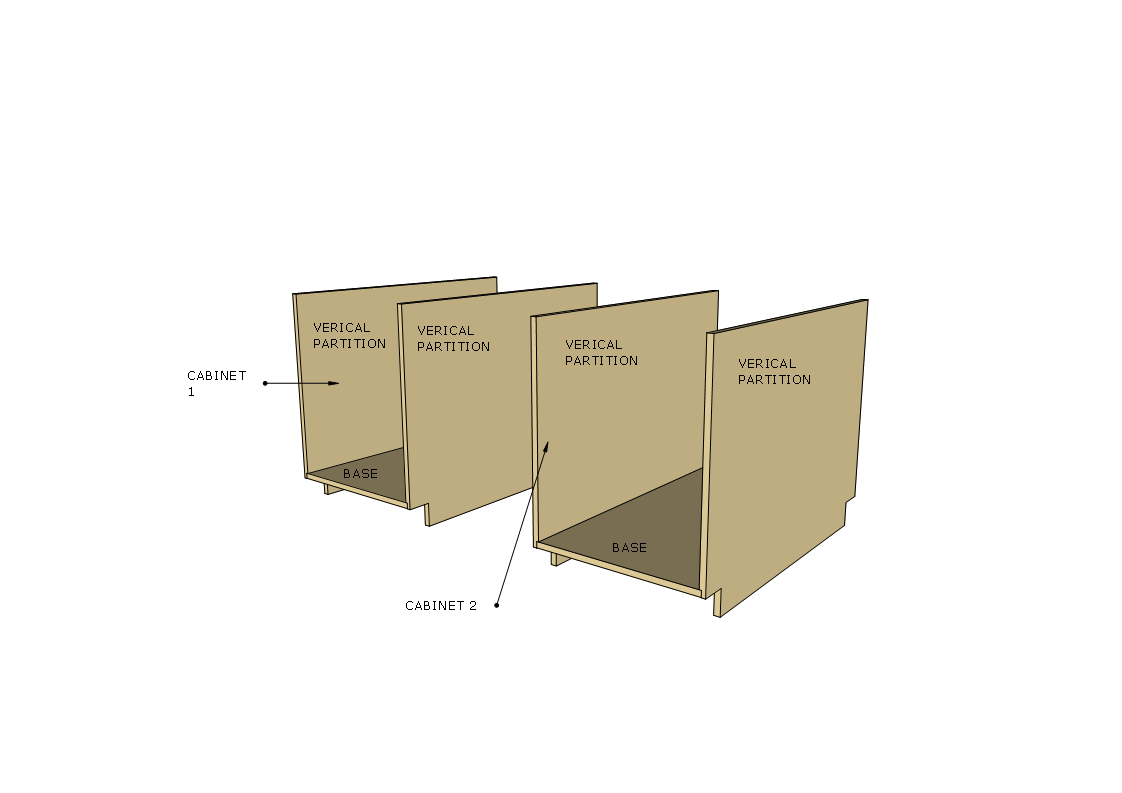
The below diagram shows you the section of the project I am working on at the moment the base frame consists of the following:

  • 4 Vertical Partitions

  • 2 Cabinet Base’s

  • 3 Top Stretchers

  • 2 Toe-Kicks

CABINET.png

So with the cabinet bases cut to size it was time to switch my attentions to the vertical partitions.

VERTICAL PARTITIONS

There are 4 partitions in total that make the sides of the cabinets, each vertical partition gets the following:

  • A dado groove measure 3/4” wide x 1/4” deep positioned 3” from the bottom of the pvertical partition which goes from the front to the back of the vertical partition so as that the base can fit inside and then I will glue and screw into position.

  • 3” x 3” notch cut out so as that I can place the toe-kick which spans the entire table base but more on that later , I used my jigsaw to cut out the notches.

NOTE: I needed to measure the plywood thickness as nowadays plywood is not the advertised 3/4” it was actually 23/32” of an inch I used my dado stack inside my tablesaw to cut out the dadoes.

Make sure that you orient each vertical partition the right way as only the inside faces of the them will receive a dado, if you don’t you will put a dado on the wrong side and the base will not fit into the cabinet

Here is the measurements needed to perform all the tasks on the vertical partition

Here is the measurements needed to perform all the tasks on the vertical partition

Here you can see the toe kick notches cut out and the dado groove running from the left to right side.

Here you can see the toe kick notches cut out and the dado groove running from the left to right side.

A closer look at the vertical partition

A closer look at the vertical partition

Although Marc Spagnulo didn’t add screws to secure the base I will be using screws and glue, this line indicates the center line of the dado I will be counter-sinking 1-1/4” screws into this outside face of the panel I will also come back later and …

Although Marc Spagnulo didn’t add screws to secure the base I will be using screws and glue, this line indicates the center line of the dado I will be counter-sinking 1-1/4” screws into this outside face of the panel I will also come back later and plug the holes with probably oak plugs.

Here you can see the pre-drilled counter-sunk holes.

Here you can see the pre-drilled counter-sunk holes.

Here is an image displaying the toe-kicks all cut out they measure 3” x 3”

Here is an image displaying the toe-kicks all cut out they measure 3” x 3”


ASSEMBLE CABINET’S

With all the components cut to size for the cabinet bases it was time for some assembly. Here is the order I did the assembly:

  1. Started working on the left side cabinet by placing glue on one of the vertical partitions dadoes

  2. I also cut some temporary stretchers to balance the base of the cabinet while I secured it with screws that I Pre-drilled holes for.

I added glue to the Dado in one of the vertical partitions

I added glue to the Dado in one of the vertical partitions

Here you can see the temporary support stretchers I screwed to the cabinet side. This way when I lie the base on the sides Dado it can rest on the supports as I secure the base with screws

Here you can see the temporary support stretchers I screwed to the cabinet side. This way when I lie the base on the sides Dado it can rest on the supports as I secure the base with screws

Here is what the cabinet carcass frame looks like all assembled, just checking for square and everything looks great.

Here is what the cabinet carcass frame looks like all assembled, just checking for square and everything looks great.

Right side cabinet all complete as well. Starting to get places.

Right side cabinet all complete as well. Starting to get places.

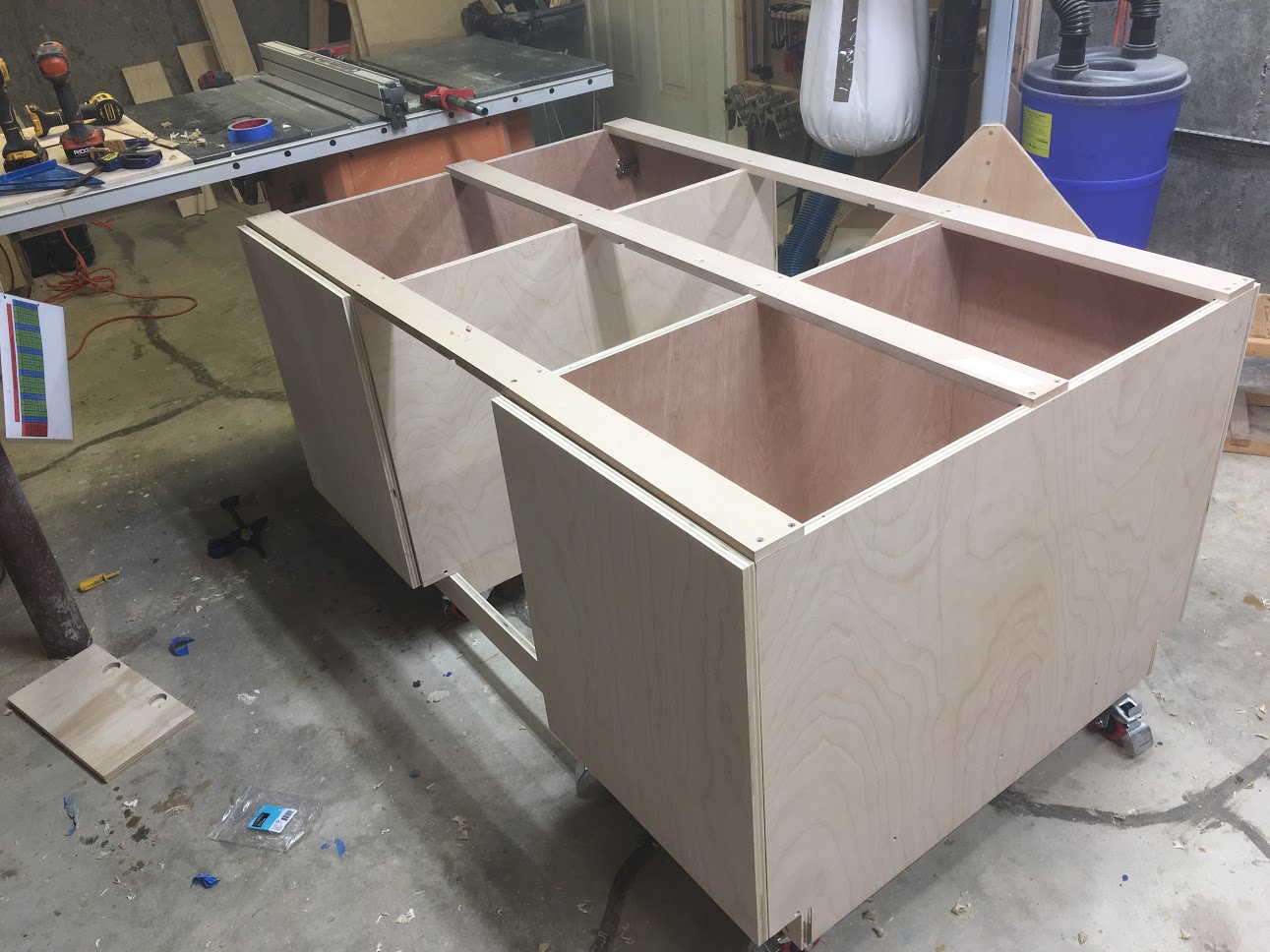
I positioned both cabinets with the space between them for the bank of drawers I will be placing in there, just making sure everything lines up.

I positioned both cabinets with the space between them for the bank of drawers I will be placing in there, just making sure everything lines up.


GETTING MOBILE : ADDING CASTERS

Almost every piece of furniture in my shop is mobile as I think that is extremely important, because you never knw when you need to move things around. Especially with projects this big it takes a lot of staging space so as that your comfortable when in the assembly stages of big projects like this.

I will be adding a total of eight 3” casters, 4 on each cabinet.

Here are the steps I took in attaching them:

  • Attached 3” high glue blocks which are basically 2 pieces of 2x4 glued together then Predrilled and attach to the underside of the base cabinet.

  • Using hex head bolts I will be securing the 3” casters to the the glue blocks.

Here is the 3” thick glue blocks, you see if I didn’t add the glue blocks I would not have enough clearance to get around the toe-kicks when they ae eventually attached.

Here is the 3” thick glue blocks, you see if I didn’t add the glue blocks I would not have enough clearance to get around the toe-kicks when they ae eventually attached.

Finally here are the casters attached

Finally here are the casters attached


ATTACHED STRETCHERS & TOE KICKS

Screenshot - 2_17_2019 , 3_36_35 PM.png

As you can see from the above diagram the cabinet carcasses are held together by 3 stretchers that go over the top of the cabinets, and using the toe-kick pies to securing the unit from the bottom.

THE STRETCHERS:

The stretchers are positioned on the front and back of the cabinets and one in the middle, before I cut the 3” wide stretcher pieces I cut a series of rabbets at both ends of the workpiece and then 2 in the center. Make sure to measure accurately the distance from left to right side of each cabinet and then measurement will be transferred to the 3/4” workpiece.

Next using cut the rabbets and dadoes, I used my dado stack inserted into my table saw. Once all these grooves are cut , I cut them to final size of 3”. Finally I predrilled the top side of the stretchers and secured them to the cabinet frames.

These piece are vitally important for 2 reasons.

  • The attach the 2 cabinets together into one unit

  • They also keep the cabinets plum and square.

Here you can see the ends of one of the stretchers with the rabbet cut out and secured in place.

Here you can see the ends of one of the stretchers with the rabbet cut out and secured in place.

Here are the 3 stretchers attached to the cabinets.

Here are the 3 stretchers attached to the cabinets.

THE TOE-KICKS

Usually most cabinets receive toe-kicks for decorative reasons, but I decided to use as part of the structure of the cabinet, the other reason people design toe-kicks is so they don’t stub their toes when at the cabinet, but I really didn’t need the toe kicks as I have the cabinets up on 3” casters, but as I said I needed the structural convenience of this piece.

The easiest way I attaching the toe-kicks was to put the cabinet on its back that way I could have easy access to securing the toe-kick.

The easiest way I attaching the toe-kicks was to put the cabinet on its back that way I could have easy access to securing the toe-kick.

Here is the image of the cabinet in proper orientation with the toe-kick attached and in place.

Here is the image of the cabinet in proper orientation with the toe-kick attached and in place.


MADE DOOR/CABINET PULLS

Shop projects are a great way of experimenting with lots of things, I decided to make my own cabinet pulls because to be honest I didn’t like the once at the big box stores and I had some solid oak on hand and figured that wood would give a nice contrast to the birch once all completed.

I went online and found a great article on how to make them and you can find the article here

Here is my plans that I made on Sketchup.

Here is my plans that I made on Sketchup.

All finished, looks great, I needed t make 12 of these as I will be using them on my doors and drawers

All finished, looks great, I needed t make 12 of these as I will be using them on my doors and drawers


ATTACHED CABINET DOORS

I know that I stated that doors and drawers would be dealt with in Phase 3 but I just got the Kreg concealed hinge jig and was itching to try it out, the jig was that awesome I attached all the doors in like 60 minutes. If you use a lot of Euro 35mm concealed hinges and don’t always have access to a drill press this jig is great.

THE JIG

Here is a stock image on the jig

Here is a stock image on the jig

Lined up the jig so the left side was flush with the door, then clamped in place

Lined up the jig so the left side was flush with the door, then clamped in place

The jig comes with a stop and drill guide to keep the hole straight and plum and the stop prevents you from not going through the door.

The jig comes with a stop and drill guide to keep the hole straight and plum and the stop prevents you from not going through the door.

Hinges all attached and doors work great.

Hinges all attached and doors work great.


OUT WITH THE OLD & IN WITH THE NEW

THE OLD

IMG_4388.JPG
IMG_4390.JPG

My old assembly table served me well for more than 5 years but it is all beat up and it didn’t satisfy my storage needs anymore.

NEW

IMG_4418.JPG
IMG_4419.JPG

PHASE ONE: FINISHED

Next I will be moving onto Phase 2 : The Torsion Box I am really excited in starting this as I have never made one before. But I probably will not start it until the weekend.

PS: I posted this blog post on Saturday but when I actually saw on my site I realized that the post didn’t save right and I had to redo the post over… but this is Phase 1 in its entirety.

Catch you soon.

Torsion Box Assembly Table : Phase 1

ACTIVITIES

  • Cut down sheet goods to manegeable pieces

  • Cut Vertical Partitions to size

  • Place Dadoes in Vertical Partitions

  • Cut Toe-Kick notches

  • Assemble Cabinets

  • Attach Castors

  • Made solid oak drawer/cabinet pulls

  • Attach Stretchers & Toe Kicks

  • Attach Cabinet Doors

The below diagram shows you the section of the project I am working on at the moment the base frame consists of the following:

  • 4 Vertical Partitions

  • 2 Cabinet Base’s

  • 3 Top Stretchers

  • 2 Toe-Kicks

CABINET.png

So with the cabinet bases cut to size it was time to switch my attentions to the vertical partitions.

VERTICAL PARTITIONS

There are 4 partitions in total that make the sides of the cabinets, each vertical partition gets the following:

  • A dado groove measure 3/4” wide x 1/4” deep positioned 3” from the bottom of the pvertical partition which goes from the front to the back of the vertical partition so as that the base can fit inside and then I will glue and screw into position.

  • 3” x 3” notch cut out so as that I can place the toe-kick which spans the entire table base but more on that later , I used my jigsaw to cut out the notches.

NOTE: I needed to measure the plywood thickness as nowadays plywood is not the advertised 3/4” it was actually 23/32” of an inch I used my dado stack inside my tablesaw to cut out the dadoes.

Make sure that you orient each vertical partition the right way as only the inside faces of the them will receive a dado, if you don’t you will put a dado on the wrong side and the base will not fit into the cabinet

Here is the measurements needed to perform all the tasks on the vertical partition

Here is the measurements needed to perform all the tasks on the vertical partition

Here you can see the toe kick notches cut out and the dado groove running from the left to right side.

Here you can see the toe kick notches cut out and the dado groove running from the left to right side.

A closer look at the vertical partition

A closer look at the vertical partition

Although Marc Spagnulo didn’t add screws to secure the base I will be using screws and glue, this line indicates the center line of the dado I will be counter-sinking 1-1/4” screws into this outside face of the panel I will also come back later and …

Although Marc Spagnulo didn’t add screws to secure the base I will be using screws and glue, this line indicates the center line of the dado I will be counter-sinking 1-1/4” screws into this outside face of the panel I will also come back later and plug the holes with probably oak plugs.

ASSEMBLE CABINET’S

With all the components cut to size for the cabinet bases it was time for some assembly. Here is the order I did the assembly:

  1. Started working on the left side cabinet by placing glue on one of the vertical partitions

  2. I also cut some temporary stretchers to balance the base of the cabinet while I secured it with screws that I Pre-drilled holes for.

I added glue to the Dado in one of the vertical partitions

I added glue to the Dado in one of the vertical partitions

Here you can see the temporary support stretchers I screwed to the cabinet side. This way when I lie the base on the sides Dado it can rest on the supports as I secure the base with screws

Here you can see the temporary support stretchers I screwed to the cabinet side. This way when I lie the base on the sides Dado it can rest on the supports as I secure the base with screws

Torsion Box Outfeed & Assembly Table

Hello Everyone

I have just embarked on a new project for the workshop, I am replacing my current outfeed/assembly table with another that has a few features that my current one doesn’t have I will go into that in a little while. Since I am now working full time this project is likely to take a while to complete and will probably only get some quality shop time at home during the weekends and possibly a few nights as well.

PROJECT SUMMARY

  • Project Sequence

  • Outfeed / Assembly Table features

  • Inspiration & Plans

  • Materials

  • Cabinet Carcass Section

  • Torsion Box Section

  • Cabinet Drawers & Doors


PROJECT SEQUENCE

I am tackling this huge project in a series of sequences which will be

  • Build the carcass frame (Phase 1)

  • Build The Torsion Box Top (Phase 2)

  • Build & Install Drawers & Doors (Phase 3)

PHASE 1: BASE CARCASS  FRAME

PHASE 1: BASE CARCASS FRAME

PHASE 2: TORSION BOX TOP

PHASE 2: TORSION BOX TOP

PHASE 3 : DRAWERS & DOORS

PHASE 3 : DRAWERS & DOORS


Outfeed / Assembly Table Features

This table will have the following features as you can see in the diagram below which is an exploded view of the entire table, also remember that whatever you see in the base as far as doors and drawers will be copied on the other side of the cabinet

Exploded View.png
  • 4’ x 6’ long torsion box top (basically a torsion box can be described as a table top with a honey comb insides that provides the structure needed for a very flat and non movable surface. Below you can see the structure of the torsion box on one of my plan pages that I created.(I will make the plans available after the project is built just in case I have to tweak them here and there)

  • It will also be portable as I will be adding a total of 8 casters which will be mounted to the cabinet ends of the base

  • The base cabinet will have 8 drawers (4 on each side) and 4 cabinet 2 on each side.

  • Overall there will be huge amounts of easily accessible storage to fit tools that I currently don’t have room for especially a dedicate cabinet for my air compressor


INSPIRATION & PLANS

Inspiration for this table came from Marc Spagnulo (AKA The Wood Whisperer) I came across some YouTube videos that go into great detail for the build, he also has a rough set of plans available that I will post links too below. I needed to tweak the dimensions for the table to suit my table-saw height.

Basically his design broke the project into two sections which were

  • The Cabinet Build

  • The Torsion Box Build

How to make a Torsion Box Assembly Table. A method learned from David Marks at http://djmarks.com When assembling projects, nothing beats a wide and spacious dead flat surface. And one of the easiest and most efficient ways to create a dead flat surface is by constructing what is known as a torsion box.

MATERIALS NEEDED

There are a lot of materials to be purchased for this project and can be considered and expensive build but if you break the project down into sections the cost will not hit you all at once, at least that is what I am doing. Below is what you will need to build this table. Since I am talking the cabinet base first I got the 3 full sheets of plywood as that will be enough to build the cabinet base, you will need to get a 1 sheet of 1/2” plywood for the drawer bottoms but that can be gotten later on.

Materials List.png

PHASE 1: BASE FRAME


TODAYS ACTIVITIES

  • Broke down the 3 sheets of plywood to more manageable sized pieces, I used a number system on broken down panel’s so as that I knew what each panel was to be used for

  • Started working on the base cabinet , this will have a lot of work and probably will be the lengthiest part of he build. I cut all 4 Vertical partitions to final size