

So now that I have made both the left and right sides of the flower box Phase 3 deals with the Front of the Box. This phase probably has the most work since its the most visual piece of the box. In some ways the front bares some similarities to the sides in that it is basically a frame and panel design but with a lot more panels.
I broke this phase down into the following steps:
The parts
Joinery of the Stiles and Rails
Making the panel
Additional Joinery
Some Router Work
Assembly
THE PARTS
There are quite a few parts to making the front and they are:
Left & Right Stiles
Top & Bottom Rails
10 Panels
Below you can see the plans and the actual workpieces I needed to make the front.


JOINERY OF THE STILES & RAILS
CUTTING THE GROOVES
Just like I did in making the sides the front is basically the same, I needed to cut grooves on both rails and both stiles, the only difference in making the front is that the rails are a lot longer.
Although I am showing the rail in this image its because I need to cut a groove along the inside edges of the all parts. Basically a groove is cut on the center of the workpiece and is cut all the way along its edge.
The groove is 1/4” wide x 1/2” deep and centered on the workpiece thickness, although I thought the workpiece was 3/4” thick its evident here that its not but that was my problem to remedy and hopefully your stock is actually 3/4”.
To cut the groove I installed a 1/4” wide dado stack blade in my table saw and move the rip a 1/4” away from the blade.
The grooves are cut because I will be fitting the center panel inside this frame work .

CUTTING THE RAIL TENONS
My next piece of joinery to do only applied to the rails as this is how I closed the panel off, I needed to cut a 1/2” long tenon. In this image you can see that I have my rails in a horizontal position and is back up by my miter gauge and sacrificial board to back up the cut (this reduces tear-out).
In my table saw I widened the dado stack to 1/2”, and lowered the depth of cut to 1/4” and made 2 passes on each end of the board and it revealed the tenon. This tenon is housed in the grooves that we already cut into the edges of the stiles.

THE INSIDE PANELS
To complete the frame and panel front of course we need to make the panels as there are 10 of them in total, in the previous steps we created grooves on the inside edges of the rails and stiles, these were cut to house the center panel.
As you can see I have the panel laid flat on the table saw and in the saw I have a 3/8” wide dado stack raised a 1/4” high and a sacrificial board attached to the rip fence so I don’t damage my fence). Next I run all four edges on both faces of the panel to create a tongue, these tongues on all four sides of the panel get housed in the grooves.
Although there are a total of 10 panels that make up the front 9 of the 10 are the same but the last panel is different because there is no groove cut into the right side, instead it has a tongue so the difference from the other panels is that there is a centered tongue on all 4 sides of the panel so as that it can fit the stile on the far right hand side of the front assembly.


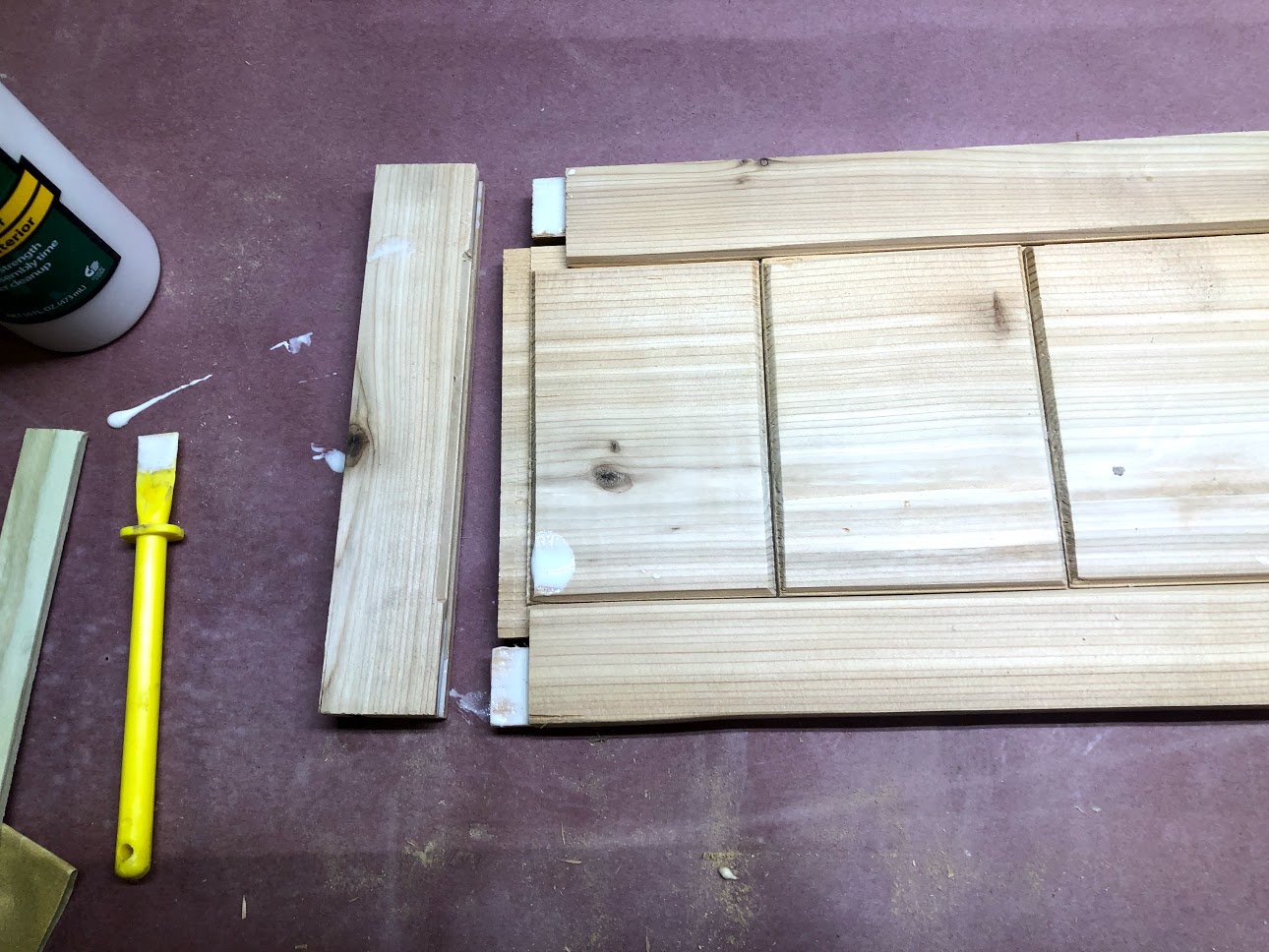
Here is an image of how the panels all fit together.
ADDITIONAL JOINERY
Since I needed a method of joining the side to the window box back and front I needed to create a joint so as that when it came to gluing up the box everywhere had a home. So I needed to cut some more grooves. In this image you can see the left stile on its face about to receive the groove that the back will connect into. Again this groove is positioned a 1/4” from the edge and is again a 1/4” wide x 1/2” deep.

ADDITIONAL JOINERY (Part 2)
You can see the connection pints that I needed to make to the front, As you can see I needed to cut an additional groove on the back side of right stile, this enabled the right side to be connected into the front assembly.

SOME ROUTER WORK
Although this is an optional step and could of simply left the side panel all flat and no character to it with a basic frame and panel design and sometimes I quite like that look. This time I decided that I wanted to define edges of the inside panel and make it stand out some more. So I used my router installed with a “V Groove” router bit.
THE STILES
These parts are some what more demanding because I don’t want to route the entire edge of the part, I only wanted the parts that came in contact with the panel visually. This is called a stop routing ad there are a ton of articles online on how to complete it the task.

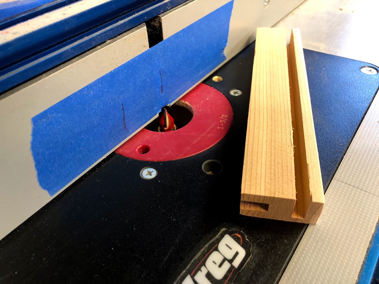
THE PANEL ROUTING
Routing the panel is easy enough as I just need to route the edges of the panel make sure your not routing the tongue as that will be hidden, add the router profile to what is left and will be exposed on the side. I just lowered the bit in the router table and just the right side of the bit is kissing the panel.

ASSEMBLY
THE GLUE UP
The only part of the front assembly that was to receive glue was the tenons on the top and bottom rails, this is because I wanted the panels inside the frame to be able to move, as I already documented season humidity can shrink and expand wood so as to avoid the panel splitting it moves freely within the rails and the stiles.
CLAMPING THE PANEL
Here you can see the front panel all assembled and the glue applied to the tenon’s, I used a decent amount of clamps to keep everything aligned and in the end I will have a very decorative front panel .


Well that wraps up Phase 3. I now have both sides and the front completed, all that is left to do is to make the back and bottom framework and then it will all be ready for the assembly phase.