router

Wooden Router Trivet Jig

WHY BUILD A TRIVET JIG??

So as of late I have been playing around with the idea of selling and shipping products on my site, but in the past I was really hesitant because of the costs associated with shipping and trying to determine how much to charge for said projects.

That was until I came across a show on YouTube about making and batching out certain projects for sale with minimal cost and time constraints. So that is how I came up with making Trivets because of a couple of reasons.

  • Small (Low shipping weight)

  • Can be made with a variety of woods

  • Can batch 10 or so in a day (without applying finish)

  • I already had an Etsy shop to sell from

Trivet Jig Design

I would love to take credit for this jig but unfortunately it wasn’t me, I came across this jig online at www.rocker.com , the jig’s concept is really easy to comprehend. It’s basically a trammel on a base, the base has 2 fences that hold the trivet blank and you adjust where the slots are cut with spacer blocks. Ill explain in more detail in a later part in this blog.

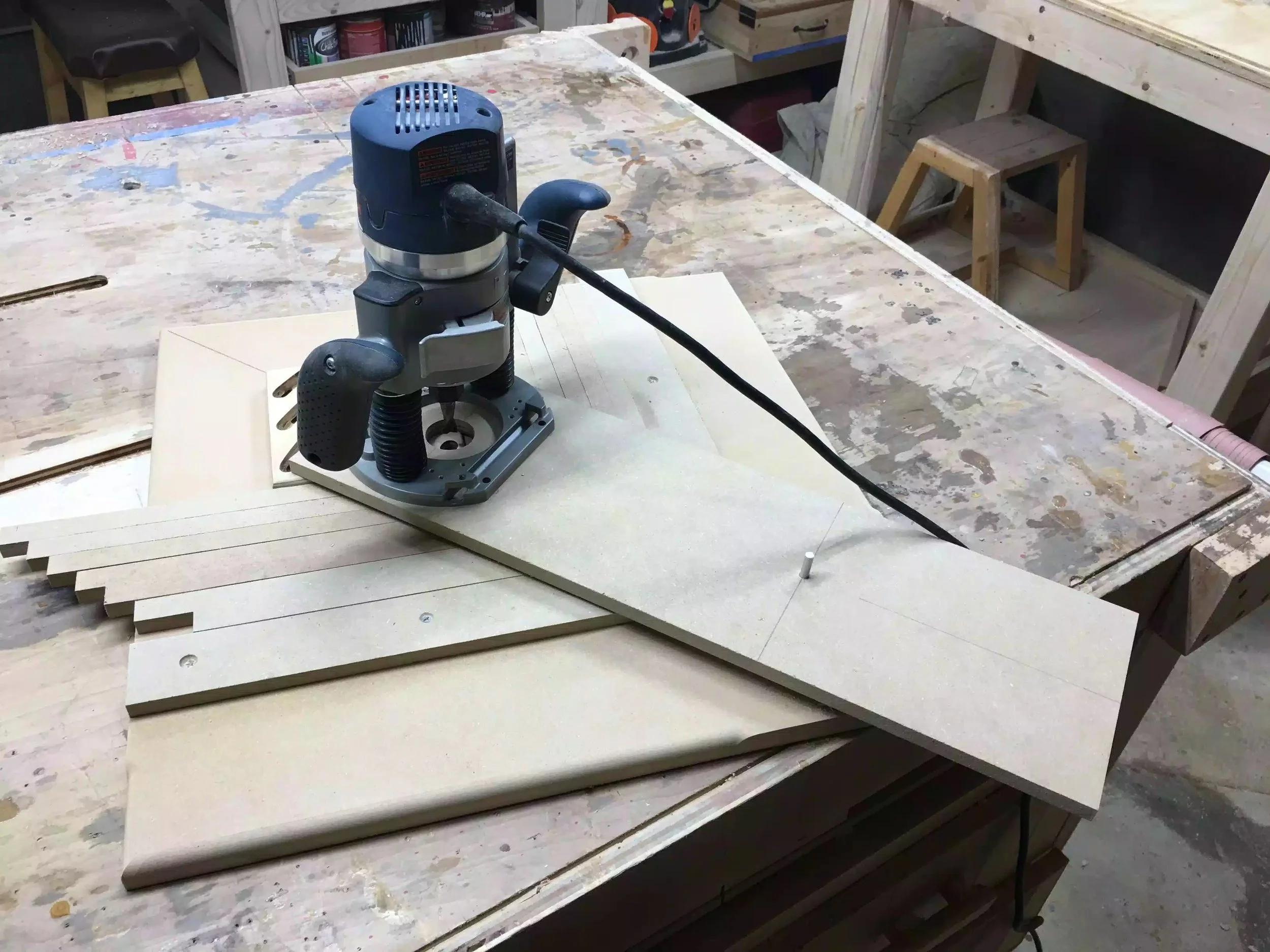
Here is the completed jig, its basically a base that has 2 fences that form a 90° corner where the trivet gets positioned, and held in place with the fences.

Here is the completed jig, its basically a base that has 2 fences that form a 90° corner where the trivet gets positioned, and held in place with the fences.

Here is a picture of the jig with the trivet blank positioned between the fences, I also used self adhesive sand paper to help keep the blank positioned while using the router.

Here is a picture of the jig with the trivet blank positioned between the fences, I also used self adhesive sand paper to help keep the blank positioned while using the router.

Here is the jig in use, you can see the router attached to the pivoting arm which is how I achieve the curved grooves in the trivet.

Here is the jig in use, you can see the router attached to the pivoting arm which is how I achieve the curved grooves in the trivet.

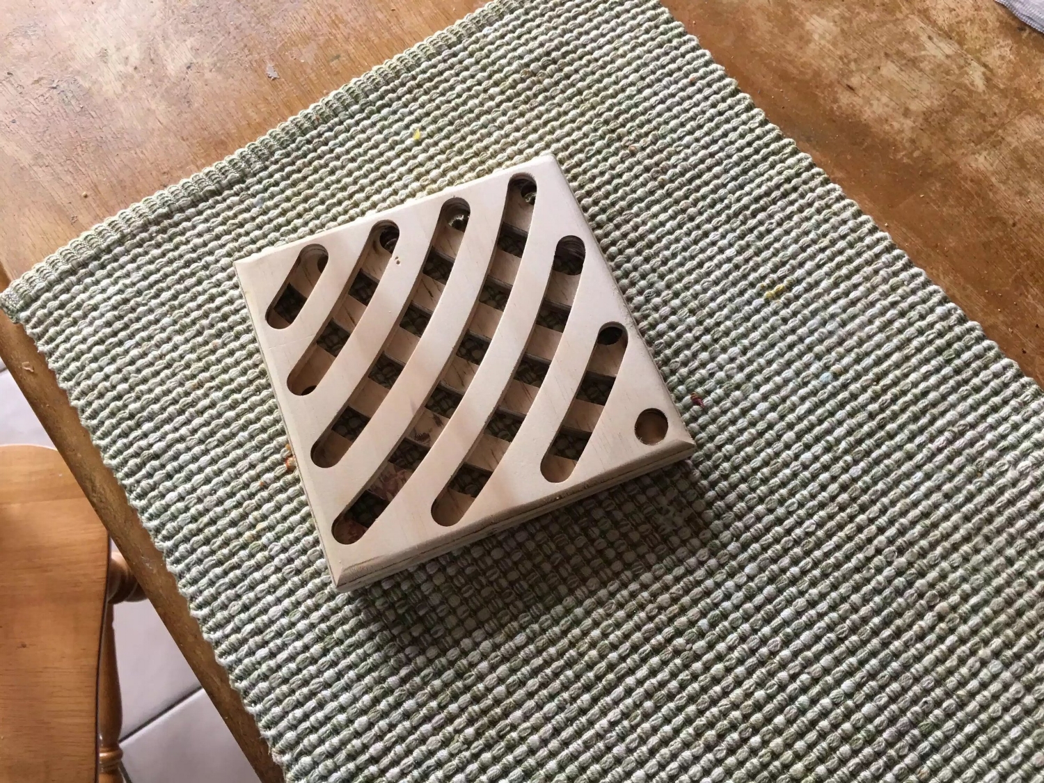
Although this is a plywood prototype of one of the designs I will be using, I am very happy with this design.

Although this is a plywood prototype of one of the designs I will be using, I am very happy with this design.

STEP BY STEP BUILD

Source Rockler.com


The trammel jig is fairly easy to assemble and, while it doesn't alter router's cutting radius, it allows you to make repetitive cutting patterns very simply. The jig is really simple to build. Start with a 22"-square scrap of 3/4" plywood or MDF, and draw a diagonal line connecting two corners. Cut a 6"-square trammel support from 1/2" scrap and bisect it with a pencil line. Fasten it to the base with glue and brads so the outermost corners of the support align with the edges of the base and the pencil marks of the two jig parts line up. Now rip a pair of 1/2" by 2" fences, cut them to an overall length of 15-5⁄8" and miter-cut one end of each to 45°.

Completed trammel jig (stock photo)

Completed trammel jig (stock photo)

JIG BUILD

Once you've put the mitered ends of the jig fence together against the support block, nail them down to secure them to the base. Butt the fences against the support piece so the tips of the miters touch. Make sure they form a square “pocket” for the trivet blanks to register against before nailing the fences to the jig base. Line the “field” area inside the fences with sandpaper attached with spray adhesive. Later, this will hold the trivets stationary as you rout them. I left the base’s outer corner bare where the trivets and spacers don’t reach it.

After mitering the corners of the fences to 45°, pin them in position and making sure everything lines up using a square. (stock photo)

After mitering the corners of the fences to 45°, pin them in position and making sure everything lines up using a square. (stock photo)

ADDING THE TRAMMEL

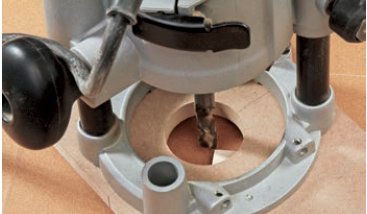
Draw a layout line 12" from the center-line of your bit to establish the pivot point of the trammel. The trammel is a scrap of 1/2" material cut 6" wide and 20" long; this width fit my router base nicely. If your router has a wider base, change the trammel width to suit it. Set the router near the trammel’s end to mark mounting holes for screws, as well as to establish where to bore a clearance hole for the router bit. Mark the trammel carefully with two layout lines: one identifying the center-point of the router bit and a second drawn 12" back from this line, before making the bit clearance hole and fastening the router to it. 

Attaching the trammel to the router (stock photo)

Attaching the trammel to the router (stock photo)

NEXT

Slide the trammel along the support block until the router bit touches the outer corner of a trivet blank to set the position of the jig. You’ll need one of your 6"-square trivet blanks to mount the trammel properly on the jig. With the router bit installed, set the trivet blank in the corner formed by the fences and balance the trammel on it and the square support block. Slide the trammel along the support until the inside edge of the bit just kisses the outer corner of the trivet

Positioning the router in order to find the pivot point on the jig (stock photo)

Positioning the router in order to find the pivot point on the jig (stock photo)

ATTACHING THE PIVOT PIN

Use the dowel's pivot point line to find where you can bore a dowel hole to complete the trammel. Make sure it lines up evenly over the support before boring a 5/16" dowel hole through the trammel and support — right into the base. Center this hole on your 12" layout line drawn previously. Now insert a 2" length of 5/16" dowel to engage the trammel’s pivot action. You’re nearly ready to start routing trivets, but first, make up 14 spacer strips from 1/2" scrap. Mine were 3/4" x 14".

Drilling the location of the pivot pin (stock photo)

Drilling the location of the pivot pin (stock photo)

MAKE SOME TRIVETS

Making your first cuts on the trivet face using a pair of spacers along the jig fences and cutting a little deeper than halfway through the blank in the first slot. Start the router and make your first cut, milling to final depth in two passes. I used a 1/2” up-spiral router bit — but any sharp straight bit should do fine. Swing the router clockwise or counterclockwise — either works fine, but keep the trammel pressed down firmly against the trivet blank to prevent it from shifting.

Begin routing the design (stock photo)

Begin routing the design (stock photo)

Continue adding and subtracting spacers and feeding your router clockwise and counterclockwise to make further cuts, but keep the trivet stationary as you pivot the router. Once you complete the first cut, pull the trivet forward, insert another pair of spacers and repeat for the second, longer “swoop.” Continue adding spacer pairs between subsequent cuts until you reach the other corner of the blank. Now flip the blank over, give it a quarter turn to establish the “X” pattern and repeat the whole routing process. This time remove one pair of spacers after each pass.

Adding spacer strips to maintain equal gaps between the grooves. (stock photo)

Adding spacer strips to maintain equal gaps between the grooves. (stock photo)

FLIP THE TRIVET

Flip the trivet and give it a quarter turn to make an "X" cutting pattern on the second face, continuing to cut them in the reverse of how you made the first side. In minutes, you’ll have your first trivet knocked out and be on to the second. Sand away any bit burn marks or fuzz, and round over the edges

The waffle pattern is coming to life. (stock photo)

The waffle pattern is coming to life. (stock photo)

THE above step by step guide is taken from the Rockler.com article as well as all the pictures, but below is a trivet that I made and looks OK, it will look even better when I actually get to use some really nice wood and not the plywood prototype that I used below.

Not too big and not too small, this prototype will look great in oak or ash.

Not too big and not too small, this prototype will look great in oak or ash.

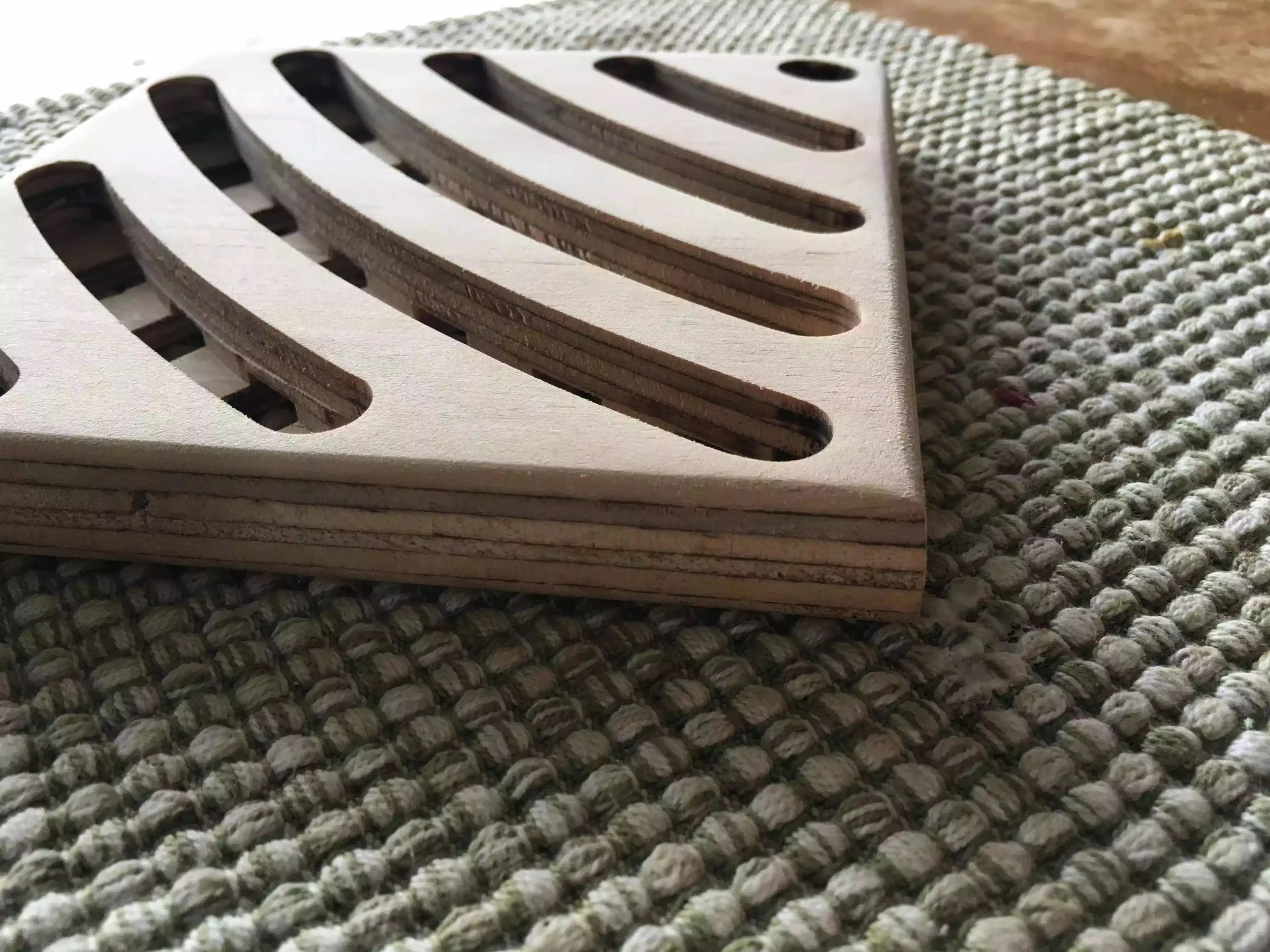
Adding a round-over to both sides of the trivet really feel great to the touch and doesnt look too bad either.

Adding a round-over to both sides of the trivet really feel great to the touch and doesnt look too bad either.

Love the dimensional aspects of this little project.

Love the dimensional aspects of this little project.

I still need to do some research on making these and eventually with a bit of luck will be able to sell them in my Etsy store… I will also be making FREE PLANS for the jig once its completed I will posit it in my shop, don’t worry I will post when their available.

Thanks for reading, and I will catch you all again soon.

Portable Sharpening Station: Day III

Today was all about the recesses that I needed to create for the sharpening stones and to be honest there was a decent amount of layout work to be done and maybe 20 minutes of me actually using my router. I gone to great detail explaining the how and the why of the steps that I took.

  • Materials Needed

  • Laying out the measurements for the template

  • Drill Press

  • Template Cut-outs

  • Dry run

  • Router time.

  • Recesses all done

MATERIALS NEEDED

I decided to use 1/2” thick MDF (Medium Density Fiberboard) for the template because of a couple of reasons, its very flat and easy to mill. I went to my local Big Box store and purchased a 2’x2’ project panel and cut it down to the size I needed.

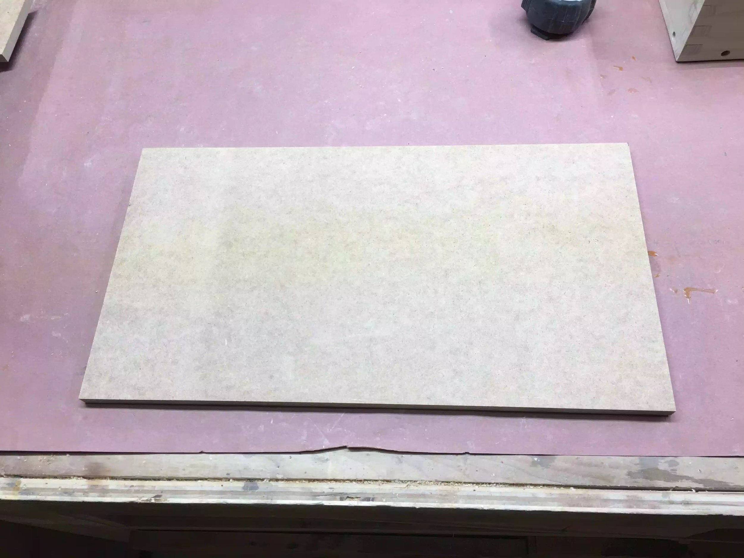
Here is the project panel cut to size, before I made all my layout lines

Here is the project panel cut to size, before I made all my layout lines

MEASUREMENT LAYOUT

The longest part of this whole part of the project was this section, laying out all the lines and determining how much offset I needed in making the template, because if you remeber I am going to be using a router template bushing to guide the router inside the template giving me my final shape.

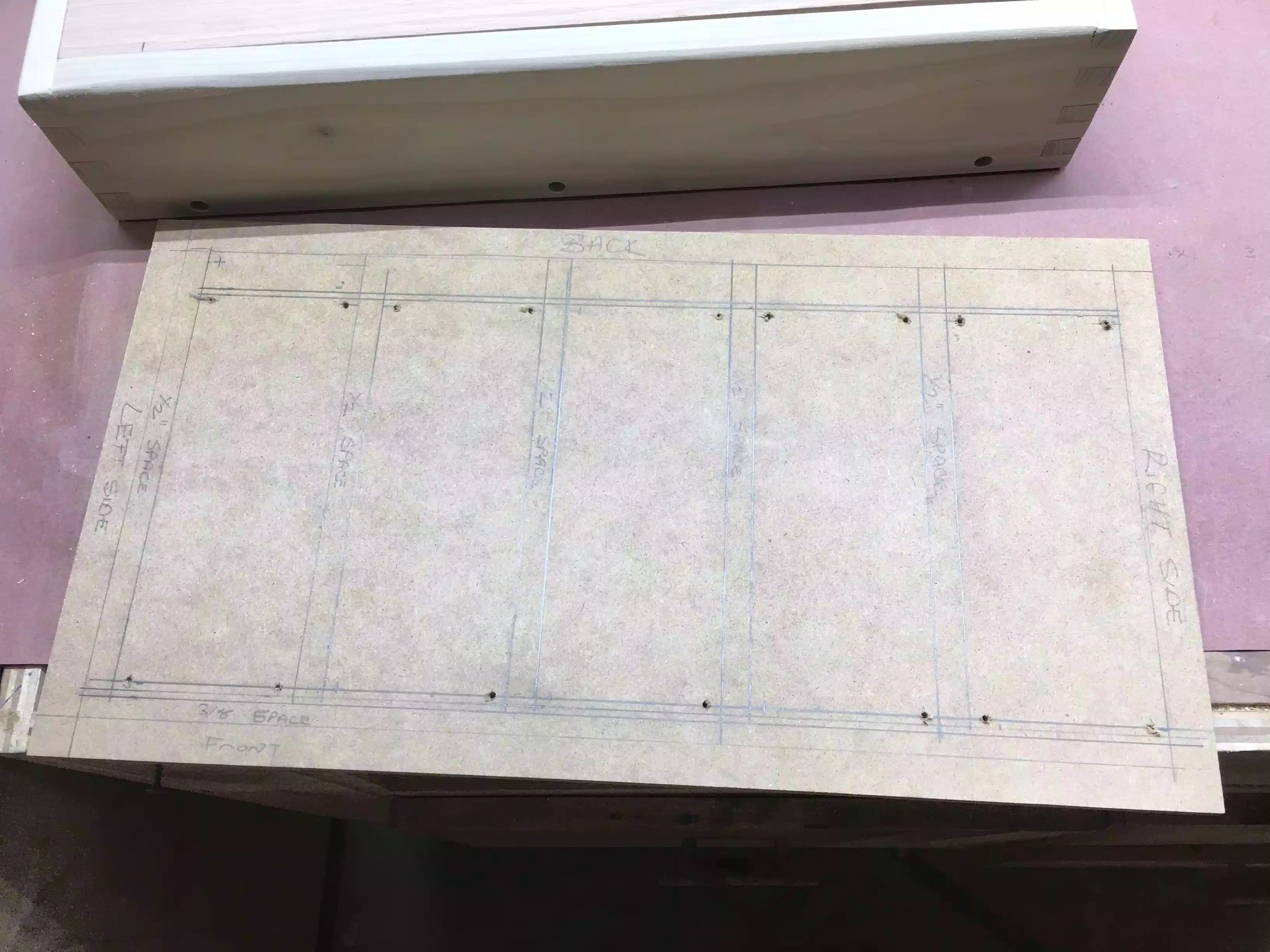
Here are some of my measurements that I am using for the template, but if you are going to make your own your measurements are probably and most likely going to be different than mine because I am using Diamond sharpening stones that are 8” x 3”. One more thing that I want to make you aware of I decided to make the template the actual size of the entire surface area of the sharpening station as it gave me more room to apply double sided tape to fix it to my tray that I will be applying the recesses into.

  • I maintained a 3/4” wide space around the perimeter of the MDF template as this represented the box beneath

  • Next to that line I came in an additional 1/2” and maintained that spacing between each of the stones and maintained this spacing all the way across the template so as that the spacing between the sides of the sharpening stones were consistent.

  • On the front edge of the template I measured 3/8” in from the first line I drew which was 3/4”.

  • One other reminder because I am a guide template bushing I needed to add 1/4” to the template to account for the offset.

  • Below you can see the measurements on the actual template.

Here is a picture describing all the measurement descriptions I gave above.

Here is a picture describing all the measurement descriptions I gave above.

DRILL PRESS

I needed to drill relief holes in the template because I will be using a jigsaw and because all the cutout are on the inside of the template I needed an entry and exit points for the jigsaw bit. So I used a 1/4” brad point drill bit so as that I could register the bigger bit because I really needed to stay inside my layout lines. I then came back with a 1/2” brad point to finish cutting all the holes, I put 1 hole on each corner of where the recesses will be cut out.

Here is an image after I used the 1/4” brad point drill bit.

Here is an image after I used the 1/4” brad point drill bit.

Here is the template after I added the 1/2” holes.

Here is the template after I added the 1/2” holes.

Here is the drill press in action drilling out the 1/2” holes, this diameter bit has just enough room for me to fit my jigsaw blade through.

Here is the drill press in action drilling out the 1/2” holes, this diameter bit has just enough room for me to fit my jigsaw blade through.

TEMPLATE CUT-OUTS

I needed to remove 5 sections of the template and to be honest there was not much to see except me using a jigsaw and dust flying everywhere, always remember to use eye protection and I always use a respiration mask to stop me inhaling he MDF dust as there is a connection with that dust and cancer.

Here is the template almost complete I needed to do a little sanding to even out the jigsaw blade marks, I also needed to square off the corners.

Here is the template almost complete I needed to do a little sanding to even out the jigsaw blade marks, I also needed to square off the corners.

TEMPLATE DRY RUN

Before I used the template on the solid oak top I decided to use it on a scrap piece of plywood so as that if I needed to fine tune the template I could do it before I started actually routing the recesses.

Here is the template on the scrap piece of plywood after using it, I needed to fine tune the template before using it on the oak.

Here is the template on the scrap piece of plywood after using it, I needed to fine tune the template before using it on the oak.

Here is the dry run on the plywood, not too bad for my first time using a template.

Here is the dry run on the plywood, not too bad for my first time using a template.

USING THE TEMPLATE

Next was to actually use the template to route the 5 recesses that I needed for the stones. When it came to deciding the bit style I wanted to use the 1/4” spiral bit but when it came to putting the bit into the router I realized that the bit was not long enough to protrude through the guide bushing, so I moved the bit a little more out of the Colette, enough so as that I went deep enough through the template and into the work-piece, the problem with that was that while I was routing the recess the bit moved out more probably because the Colette didn’t hold the bit in place and it dug deeper into the oak panel.

So I needed to come up with a plan b and that was to use 1/2” straight bit with a 3/4” OD bushing that way I could keep the template dimensions the same and still receive the exact dimensions that I needed to fit the diamond plates and it worked. The only problem was that I didn’t go as deep to get rid off the marks left from the spiral but slipping. In woodworking sometimes you face these issues and you need to find solutions to them, although I was plenty mad at the bit slipping , it was my fault that it happened and I will not be doing that again. To rectify this problem in the future I need to make sure that I have the correct size bit for the operation that I have before I actually start doing the work, a simple solution would be to purchase a router bit extension piece.

To be honest I thought about not writing about this, but woodworking has thought me to own up to mistakes because everyone makes them even the pros and mistakes make you think outside the box when trying to rectify them, at the end of the day I still achieved what I was looking for.

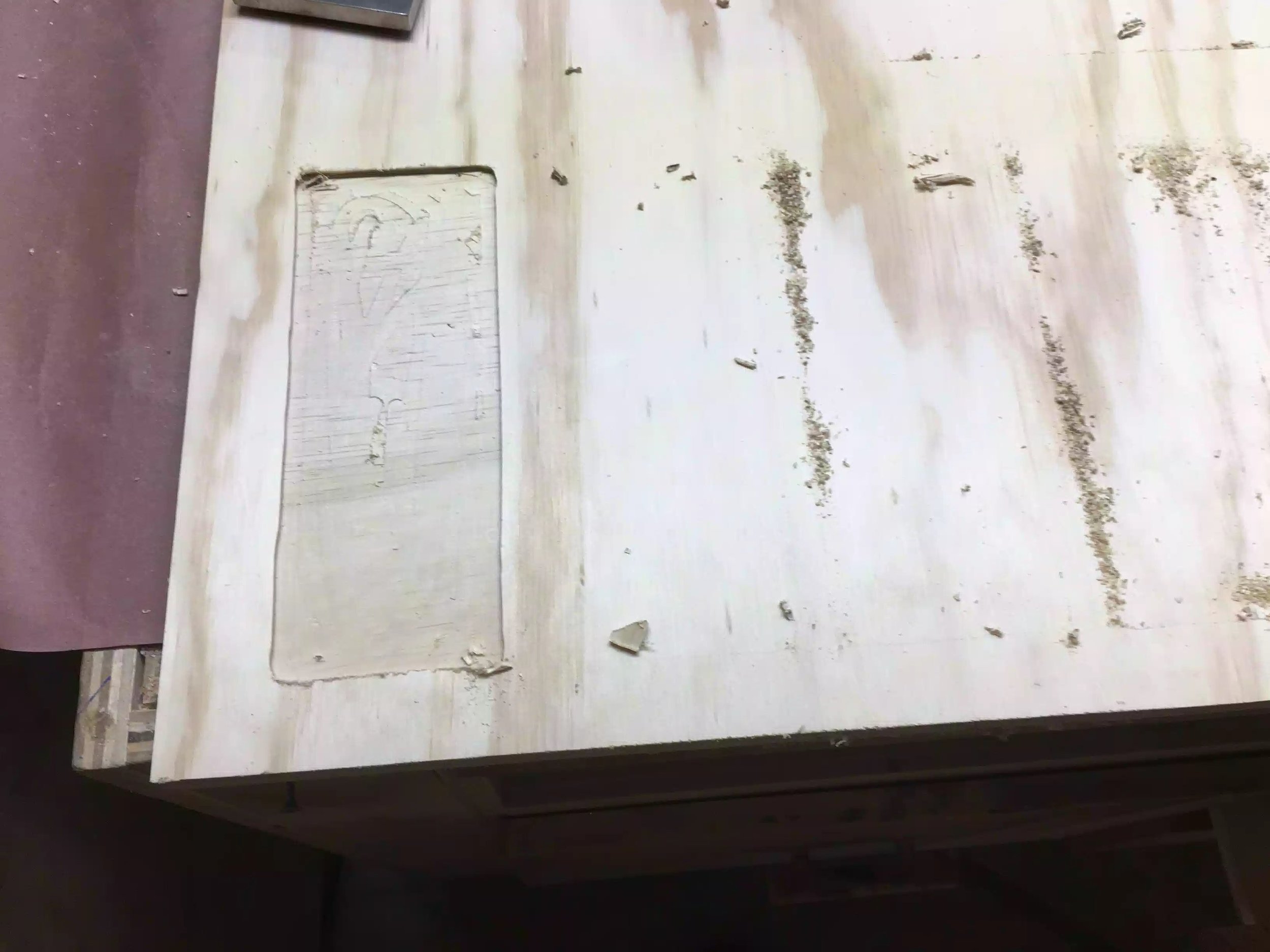
Here is a picture of the template on the oak work-piece, I used double-side tape to secure the template to the oak top.

Here is a picture of the template on the oak work-piece, I used double-side tape to secure the template to the oak top.

RECESSES ALL COMPLETE

Here are a few pictures of the finished top, you can see the stones in place, I only have 2 diamond stones right now and I need to get at least one more, I will be putting a leather strop pad on the last recesss for finishing up my sharpening process, but that comes tomorrow.

Here are 2 stones sitting in the recesses , they fit great and will not be moving around.

Here are 2 stones sitting in the recesses , they fit great and will not be moving around.

Here is the front of the sharpening station, I was thinking off adding finger pull holes to remove the sharpening stones but they are not so deep that I cant just lift them out of the recess.

Here is the front of the sharpening station, I was thinking off adding finger pull holes to remove the sharpening stones but they are not so deep that I cant just lift them out of the recess.

Here is aside view, as you can see the finger holes are deep enough to pull out the top when I need to have access to the box contents.

Here is aside view, as you can see the finger holes are deep enough to pull out the top when I need to have access to the box contents.

Well that is all I had time for today,

NEXT

  • Make a leather strop pad for the last recess, I have the leather, just need to figure out a way to add some thickness and rigidity to it.

  • Fill the screw holes with wooden plugs

  • Apply a finish to the station.

DRILL PRESS CART : DAY 3

Since I had already built the drawer frames all I needed to do today was to add the drawer bottoms.

Here is what I got done today

  • I added the drawer bases to the 5 drawers
  • Test fit 1 drawer with drawer slide 
  • Needed to overcome a measurement error

ADDING THE DRAWER BASES

I needed to make 5 drawer bases so as that I could attach them to the drawer frames. So I took the following steps to complete the drawers. I have detailed pictures below detailing each step of this.

  1.  Cut up a 1/4" thick sheet of plywood to the final dimensions to fit the drawer, since I was not doing any fancy joinery the cuts were very quick, I was basically cutting the the 1/4" plywood and using my brad nailer and glue to secure the bottom on the drawer.
Here is a picture of me cutting the plywood into smaller sections to fit the drawer base.

Here is a picture of me cutting the plywood into smaller sections to fit the drawer base.

        2.  Now that all 5 drawer bottoms were cut to size , next I wanted to draw a reference line                       1/2" in from all sides of the panel, to drive brad nails in the bottom securing them to                         the  bottom of the drawer, I used my Incra T-Ruler to accomplish this, I needed the                           brad nails inset a 1/2" because I need to use my router on the edges more about this                           in  a later step.

Here is the Incra T-rule, I used this to mark a 1/2" line around all edges

Here is the Incra T-rule, I used this to mark a 1/2" line around all edges

Here is a close up the pencil line outlining the 1/2'' reference line on the drawer bottoms, I needed to do this to all 5 panels 

Here is a close up the pencil line outlining the 1/2'' reference line on the drawer bottoms, I needed to do this to all 5 panels 

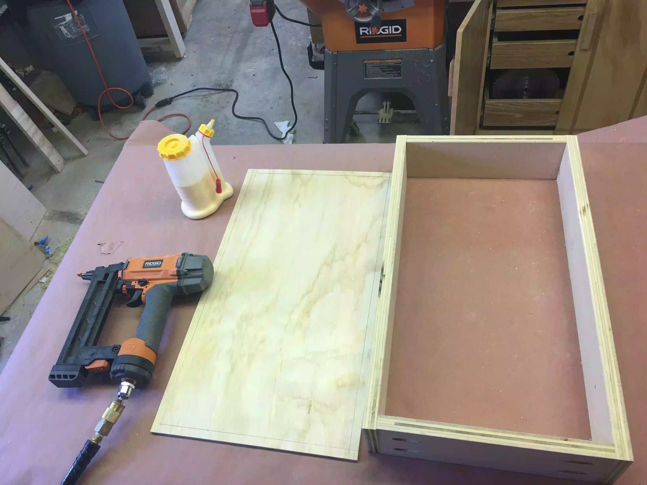
    3.  Next I needed to set -up my assembly table to secure the bases to the drawers, below                           you see what I needed. I used my pneumatic nailer with staples inside, some glue. Using                     the 1/2" line that I did in the previous step I used the arrow on the tip of my brad nailer to               reference where the nails would be entering the drawer being careful not to actually                           shoot a nail through the actual drawer base.

Supplies needed, a nailer, the bottom drawer plywood panel and glue.

Supplies needed, a nailer, the bottom drawer plywood panel and glue.

Here is a view of the bottom. I needed to sand all the bottoms and edges to remove any glue .

Here is a view of the bottom. I needed to sand all the bottoms and edges to remove any glue .

Another picture before assembly 

Another picture before assembly 

Here is a look inside the drawer

Here is a look inside the drawer

Here are all 5 drawers with bases attached one more step before there almost complete.

Here are all 5 drawers with bases attached one more step before there almost complete.

       4 .   Before I can say the drawers are finished I needed to use my palm router to add a                                chamfer to the plywood edges. I saw this trick used online and I think it is a very                                clever method to hide the plywood edges on drawers. You basically use a chamfer bit                          in   a router and go around all edges of the plywood drawer base and it removes the                            material that can be seen when the drawer is sitting in the cabinet or unit. Oh and I                          almost forgot to tell you that the brad nails were recessed because I didn't want my                            router catching the nails as I removing the plywood edges when I was going around                            the drawer base with my router.

Here you can see the palm router ready for action, its installed with a router chamfer bit.

Here you can see the palm router ready for action, its installed with a router chamfer bit.

Here is a close-up of the router with the chamfer bit. I really love this tool. Perfect for applications like this.

Here is a close-up of the router with the chamfer bit. I really love this tool. Perfect for applications like this.

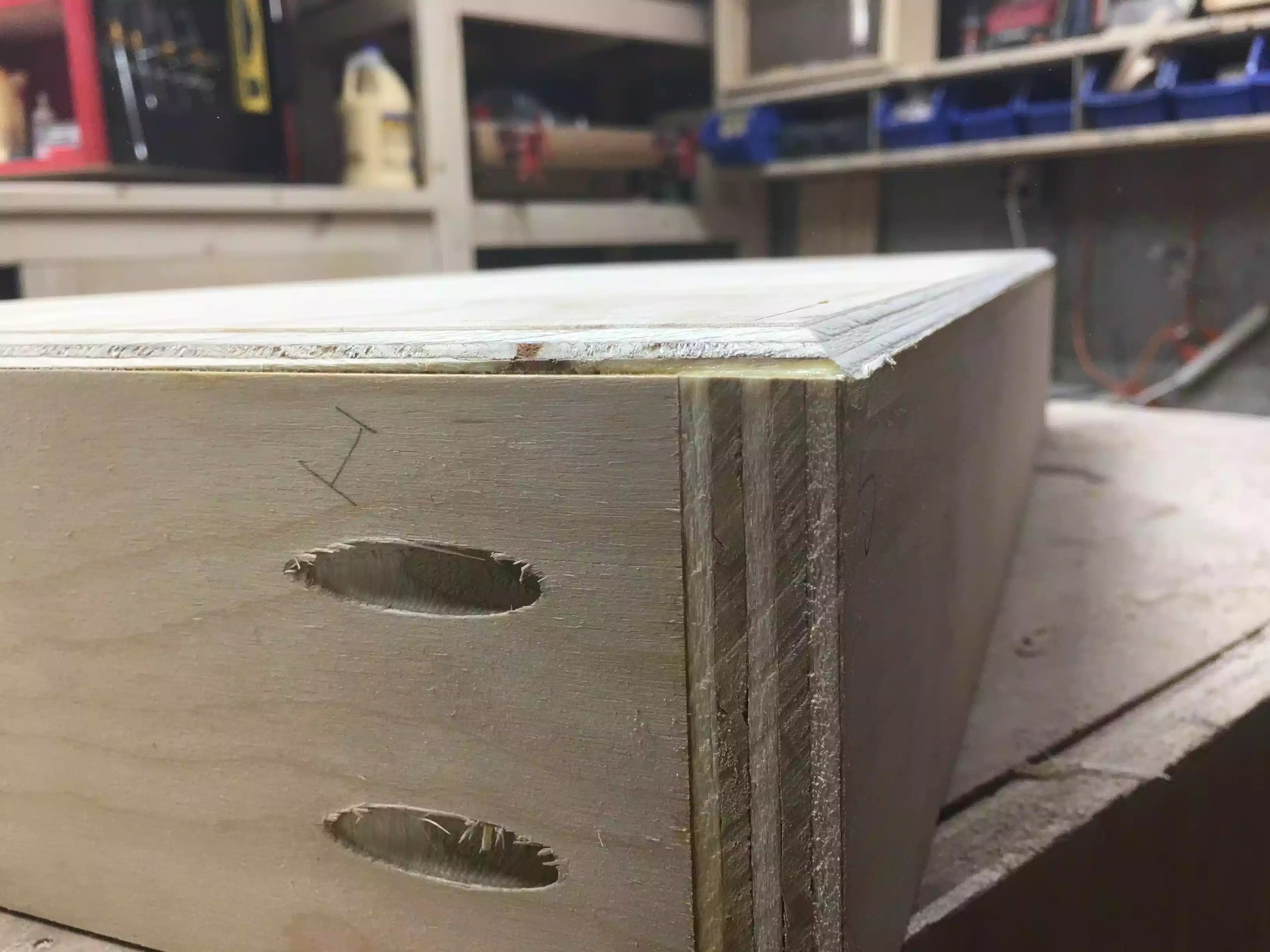
Here is a close-up of the drawer base after I added the chamfer.

Here is a close-up of the drawer base after I added the chamfer.

BEFORE picture, this is the drawer base before I added the chamfer.

BEFORE picture, this is the drawer base before I added the chamfer.

AFTER Here is the drawer base after, see no visable drawer base.

AFTER Here is the drawer base after, see no visable drawer base.

INSTALLING THE BOTTOM DRAWER

Although I didn't have enough time to install all drawers I wanted to at least install one. To my surprise the bottom drawer was a tiny bit shy (short) of engaging the right drawer slide , so I needed to remedy this by installing a shim to close the gap.

  1.  I started by preparing a spacer jig so as that I could space the drawer slides evenly going up both sides of the cabinet, to do this I measured the cabinet and luckily enough I could get away with one spacer would have equal distances between the drawer slides.  I also put a 1/4" thick piece of plywood to raise the bottom drawer up so as that it would not come in contact when the drawer was slid in and out.
  • To be honest I was quite annoyed at the drawer slide and drawer not being wide enough, I measure everything twice and followed all cut-list, I also checked for square, I think the more I think about it my problem arose because my plywood was not exactly 3/4" thick and that was something that I took for granted, usually I buy big box plywood and they are usually 23/32" and not 3/4" but I purchased this plywood else where and they told me that it was full 3/4" but lesson learnt and I am mad at myself at not making sure as I usually do, anyway we live and learn. Everyone makes mistakes, all you can do is learn from them and move on.
Here is the spacer block with the slide sitting on top, I clamped the spacer to the cabinet and pre-drilled and screwed in 3 screws, this was before I realised that the drawer was not quite wide enough.

Here is the spacer block with the slide sitting on top, I clamped the spacer to the cabinet and pre-drilled and screwed in 3 screws, this was before I realised that the drawer was not quite wide enough.

Here you can see how I remedied the bottom drawer slide issue.

Here you can see how I remedied the bottom drawer slide issue.

  • Next I pulled the drawer out on the slide and I could access two holes in the drawer slide to partially secure the drawer to the slide, I did this on both sides of the drawer and then I fianlly removed the drawer with the slide attached to the drawer and finished adding the back screws to each side, and it was complete.
Here is the bottom drawer installed and it moves perfectly now.

Here is the bottom drawer installed and it moves perfectly now.

That is as far as I got this morning thanks for reading and I catch you on the next post.

NEXT

  • I will be installing the remainder of the drawer slides and hopefully the drawers
  • Prepare the drawer false fronts to hid the pocket hole screws on the drawer fronts
  • Make the top
  • Attach Casters
  • Apply finish

PROJECT: SAND & WATER TABLE

This morning I basically finished construction on the water table, all that I needed to do was build and attach the bottom shelf, but there was a lot more to that part than anything so far here is what I needed to do.

  • Crosscut the slats for the shelf
  • Pre-drill and countersunk the slats to receive the screws
  • Dry fit slats to frame
  • Added a round over to the slats
  • Glued & Screwed the slats
  • Attach the whole shelf assembly to the table
  • Construction Phase complete

CROSSCUTTING TIME

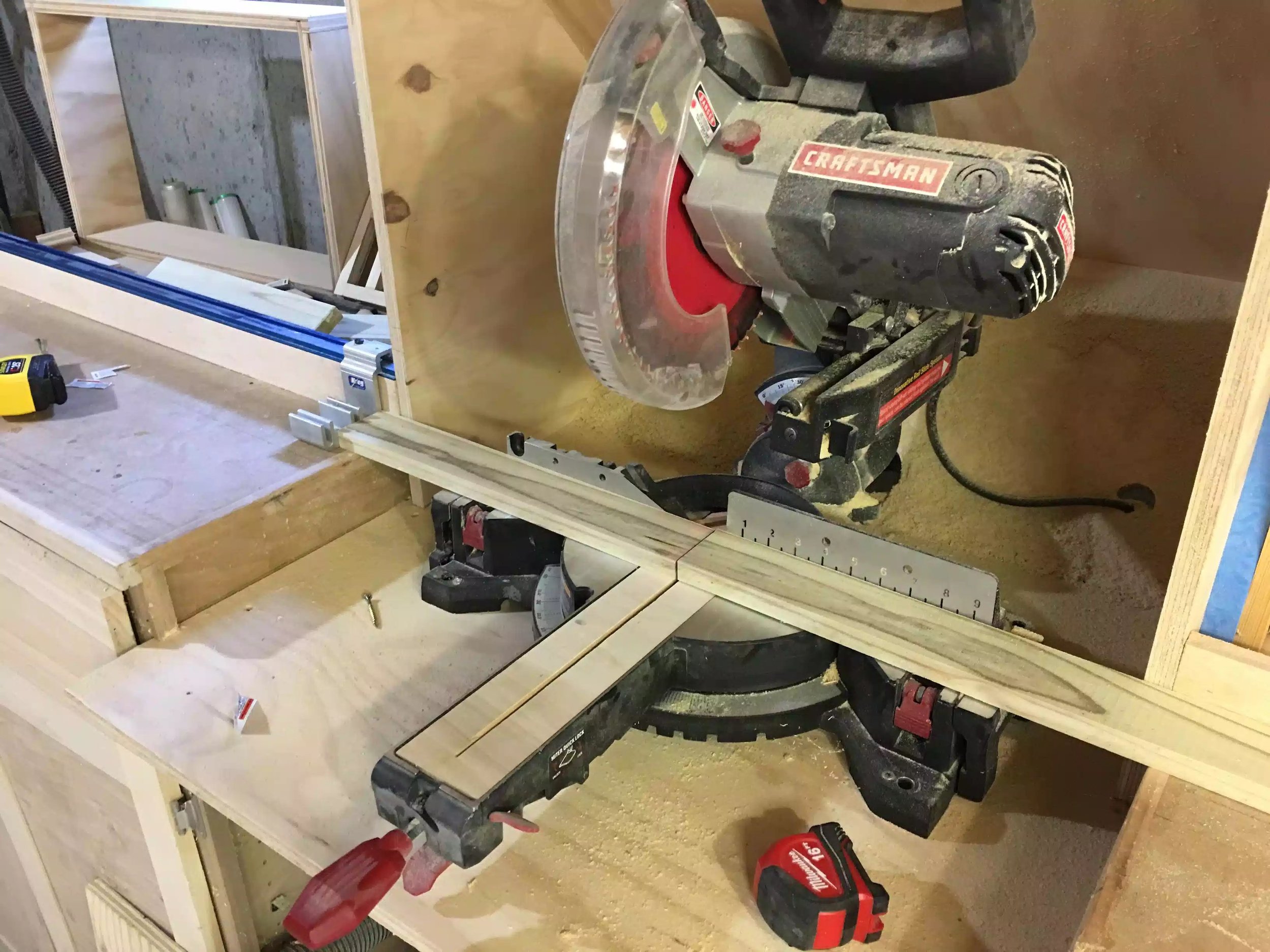
First I needed take all my 1x3 and cut them to size on my miter saw station, using a stop block on the chop saw to cut all 16 pieces to final size, below you can see a picture of my miter saw.

Here you can see the chop saw set-up using my kreg production stop that was on my top-trak on the miter saw station, this is a dream for doing repetitive cross-cuts

Here you can see the chop saw set-up using my kreg production stop that was on my top-trak on the miter saw station, this is a dream for doing repetitive cross-cuts

COUNTERSINK TIME

So now that I have all my slats cut I wanted to bury the screws beneath the surface of the wood, I was adding 4 screws per slat so that was a lot of holes to drill so I brought all the slats over to the drill press and using my home made drill press table I set up another stop block and prepared the countersinking bit for a lot of repetitive cuts.

Here is the drill press and table with the stop block clamped to my fence. I marked the pieces 3/8" from each face as they were being drilled in 3/4' thick frames.

Here is the drill press and table with the stop block clamped to my fence. I marked the pieces 3/8" from each face as they were being drilled in 3/4' thick frames.

Here is another view of the slats being prepared on the drill press.

Here is another view of the slats being prepared on the drill press.

All the slats are drilled

All the slats are drilled

DRY-FIT SLATS

I needed to determine what the spacing was for each slat so I lay out all the slats and experimented with the best spacing and I arrived at using a 3/4" space between each of the slats, you will end up with a slight larger space on the second-last slat from the end maybe 7/8" but I was OK with that.

Here is slats being spaced out evenly by 3/4" 

Here is slats being spaced out evenly by 3/4" 

ROUTER TIME

I was very excited for this step because I recently purchased a new Router from Bosch and I had only installed it in my router table last night so today was the first time I used it, and it didn't disappoint. Anyway I installed a round-over bit in the router as I was using it to apply a profile around 3 edges of each slat and it came out great, took any sharp edges and turned them into soft rounded edges, a necessity for anything that you make for children.

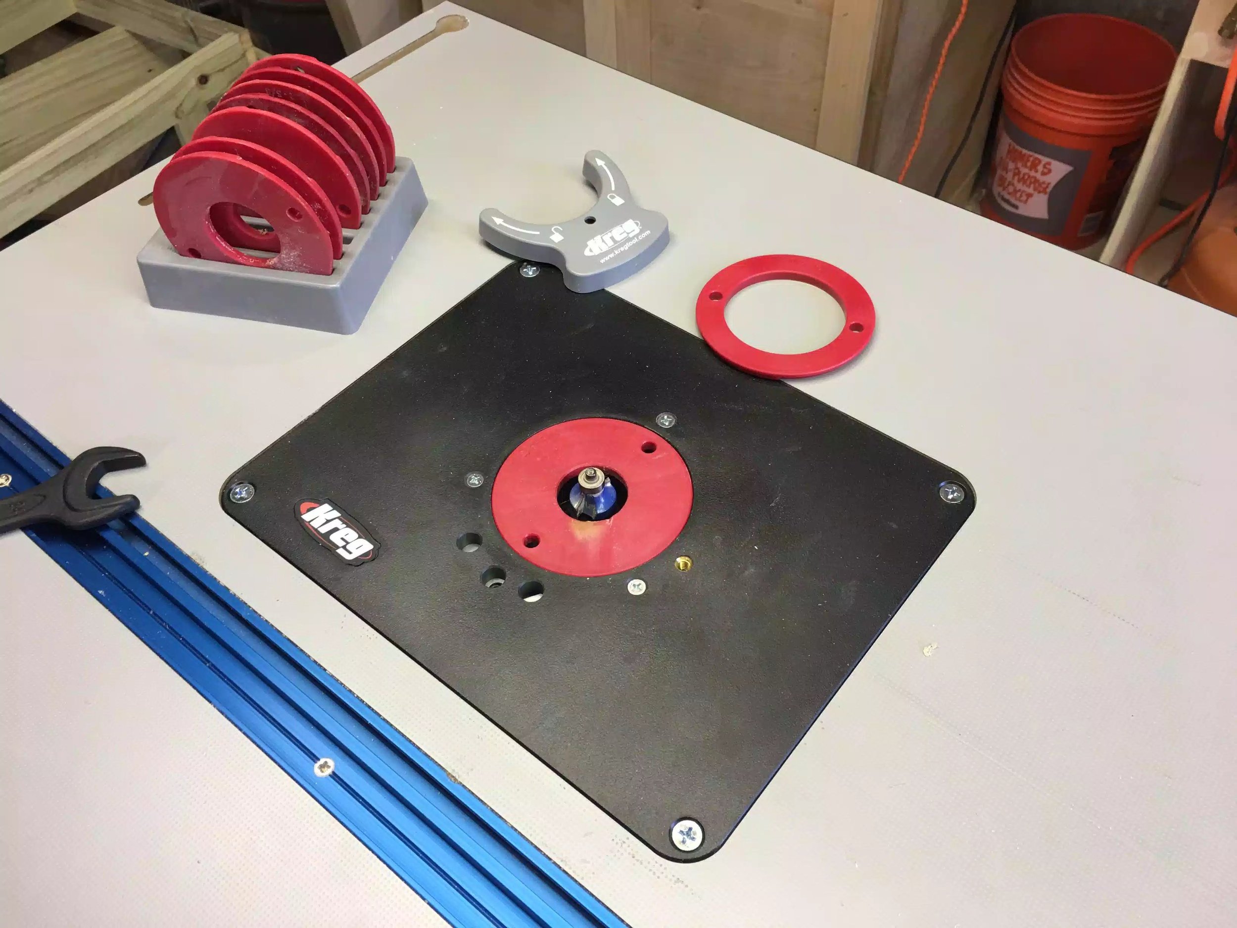
Here is my router table top, I just inserted the round over bit

Here is my router table top, I just inserted the round over bit

Here is the router under the table, its really powerful and has an awesome feature that let's me adjustments in bit height from the top of the table

Here is the router under the table, its really powerful and has an awesome feature that let's me adjustments in bit height from the top of the table

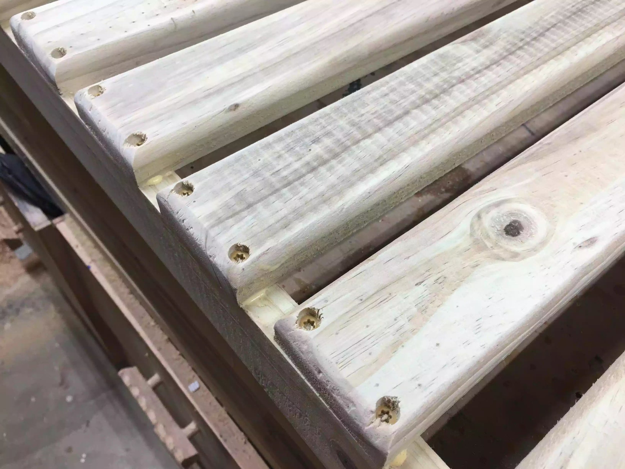
Here is a close-up of the rounded edges, although this pic was taken as I was securing them to the frame.

Here is a close-up of the rounded edges, although this pic was taken as I was securing them to the frame.

SECURING THE SLATS

So now that all the slats were milled it was ready to secure them to the frame, I used Titebond wood glue and 1 1/4" exterior screws to secure the slats in position. I used a 3/4" thick piece of wood as a spacer and just glued and screwed each piece until the shelf was finished. After the slats were installed I sanded the shelf with 220 grit sand paper in my orbital sander.

Here is the spacer I used to space each slat while I glued and screwed each slat to the bottom frame

Here is the spacer I used to space each slat while I glued and screwed each slat to the bottom frame

Shelf finished. Looks nice I am wondering should I finish it maybe a spar urethane on it

Shelf finished. Looks nice I am wondering should I finish it maybe a spar urethane on it

ATTACHING THE SHELF

Now that the bottom shelf is complete I needed to attach it to the legs, because the bottom shelf fits inside the legs and screwed, I needed to devise  a method of resting the bottom shelf assembly in place to screw into the screws. So to achieve this I cut spacers to act as ledges for the shelf to rest on temporarily and screw them home.

Below are the pictures depicting the method I used, pictures are always vetter at describing something than words so here you are, please remember that the table is upside down in these pictures.

Here is the spacer clamped to the leg with a clamp, I added 1 of these assemblies to each leg, they are resting on the bottom edge of the top frame

Here is the spacer clamped to the leg with a clamp, I added 1 of these assemblies to each leg, they are resting on the bottom edge of the top frame

Here are all 4 spacers clamped to the legs

Here are all 4 spacers clamped to the legs

Finally here is the bottom shelf assembly turned upside down and resting on the spacers , all that was left was to screw them home

Finally here is the bottom shelf assembly turned upside down and resting on the spacers , all that was left was to screw them home

CONSTRUCTION & BUILD COMPLETE

Adding the bottom shelf completed the build phase of this project and it looks great, I still need to sand the whole unit down to 220 grit sandpaper, I was going to paint the unit but because it is pressure treated it doesnt take kindly to paint as the wood is still very moist and probably will remain that way for some weeks/months.

Below are some of the pictures of the unit completely assembled and it looks great

Here is the assembled water table, looks great and I am sure my son will get plenty of enjoyment out of it

Here is the assembled water table, looks great and I am sure my son will get plenty of enjoyment out of it

You can see the containers that the water will go into, just a suggestion but I might adjust the dimensions of the table by a little and possibly use a thicker piece of wood for the divider because I can not get the lids on the containers easily as …

You can see the containers that the water will go into, just a suggestion but I might adjust the dimensions of the table by a little and possibly use a thicker piece of wood for the divider because I can not get the lids on the containers easily as they bump into each other

NEXT

  • Sand the entire unit smooth
  • I will add the round over detail to the front of the top frame, thinking about adding the round over to the edges of the legs on the non tapered sides