


So my wife asked me to make something that my 5 year old son could use with his Lego and I wanted to make him one of those Lego tables with drawers but honestly had no where to put one so I did some research online and found this nifty little project where it is basically a tray that you can set on the floor and build on and when it is not in use he can just slide it under his bed.
I didn’t make any plans for this and pretty much made it on the fly using some scraps I had lying around the shop I did need to get some materials and they are listed in this post.
This project should only take 3 stages and Part one is below:
WHAT I DID TODAY
Purchased materials
Cut pieces to size
Pocket Holes
Router Time
Assembling the tray
Router Time 2.0
A little paint
PURCHASE MATERIALS
I went to my local big box store and Target o get some supplies and here is what I got
(4) Lego base-plates (10”x10”)
24” x 24” x 3/4” plywood panel
Gorilla Glue
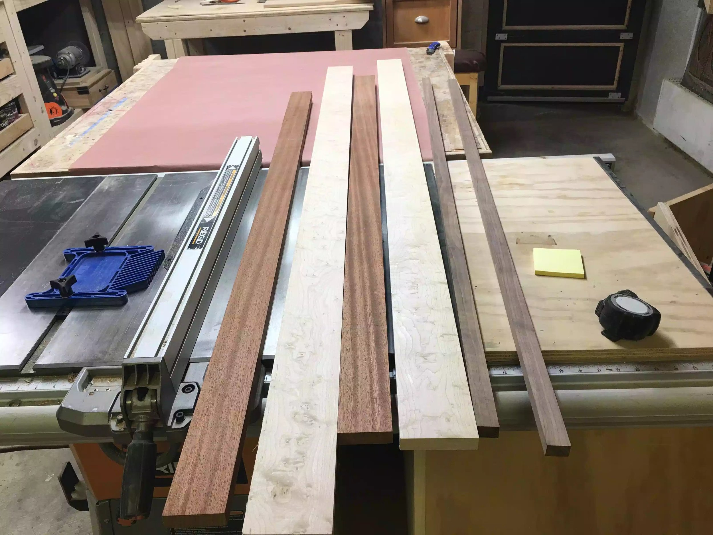
I used scrap oak and poplar but you will need a piece of 1”x2” x 8” lumber.
(2) Utility handles
Pocket hole screws 1-1/4”
Furniture Pads

Here are all the supplies I got.

Here are the felt pads, screws and 2 handles.
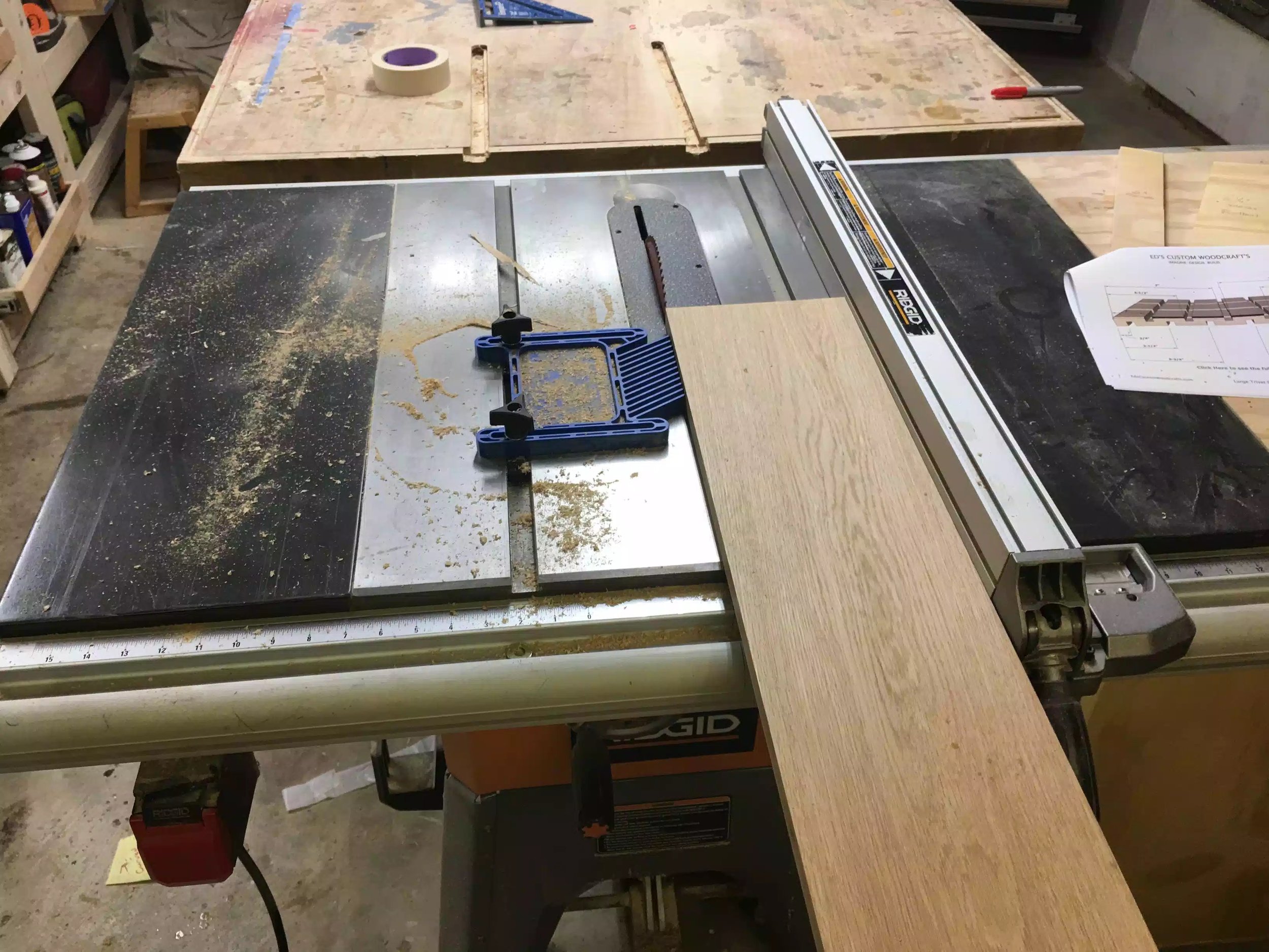
CUT PIECES TO SIZE
In order to figure out what all the dimensions needed to be for all the parts and the plywood panel I needed to open all the Lego base-plates and get the overall size and it worked out to 20-1/8” square.
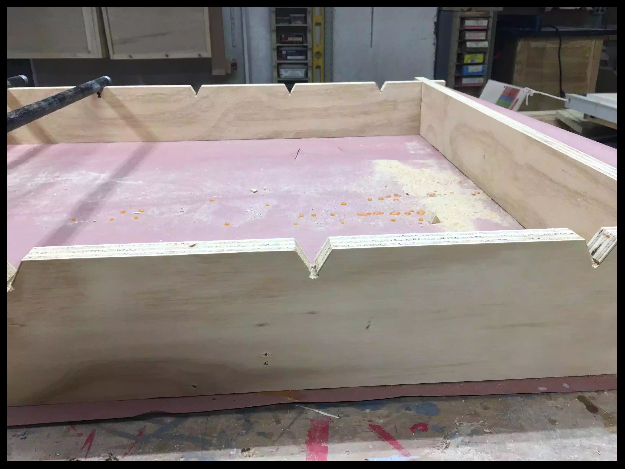
so I cut the 3/4” plywood panel to 20-1/8” square on the table saw, and then cut all the wood strips which make up the frame that surrounds the panel.

Here is the wood pieces getting chopped to final size.

Here is the plywood cut to final size
POCKET HOLE TIME
In order to attach the outside frame pieces to the base I needed to added a joinjery system so I decided to keep it easy and just add pocket holes so I just add screws to attach the sides while the glue sets up.
I use the Kreg K4 jig and made a station for it where all my accessories for the jig are stored. So I placed 4 pocket holes on each side, below you can see the finished panel and the K4 station.

Here is the finished pocket hole base

Here is one image of Kreg K4 pocket hole system that I used

Here is another image of the Jig
ROUTER TIME
I actually used the router twice in this build, I wanted to add my sons name to the outside edges of the frame so I used my Palm router to freehand his name but before I did that I needed to add some outlines of where I wanted to position the name.

Added outlines and even spaces of where I wanted the letters to go.

Using my palm router with a 1/4” upcut router bit to carve the letters in.

Next I used a sharpie marker to write the letters in, also gives me a visual guide when using the router.

Finally his name got carved, I will also adding black paint to the letters to make sure they stand out.
ASSEMBLING THE TRAY
I took the following steps to assemble the tray:
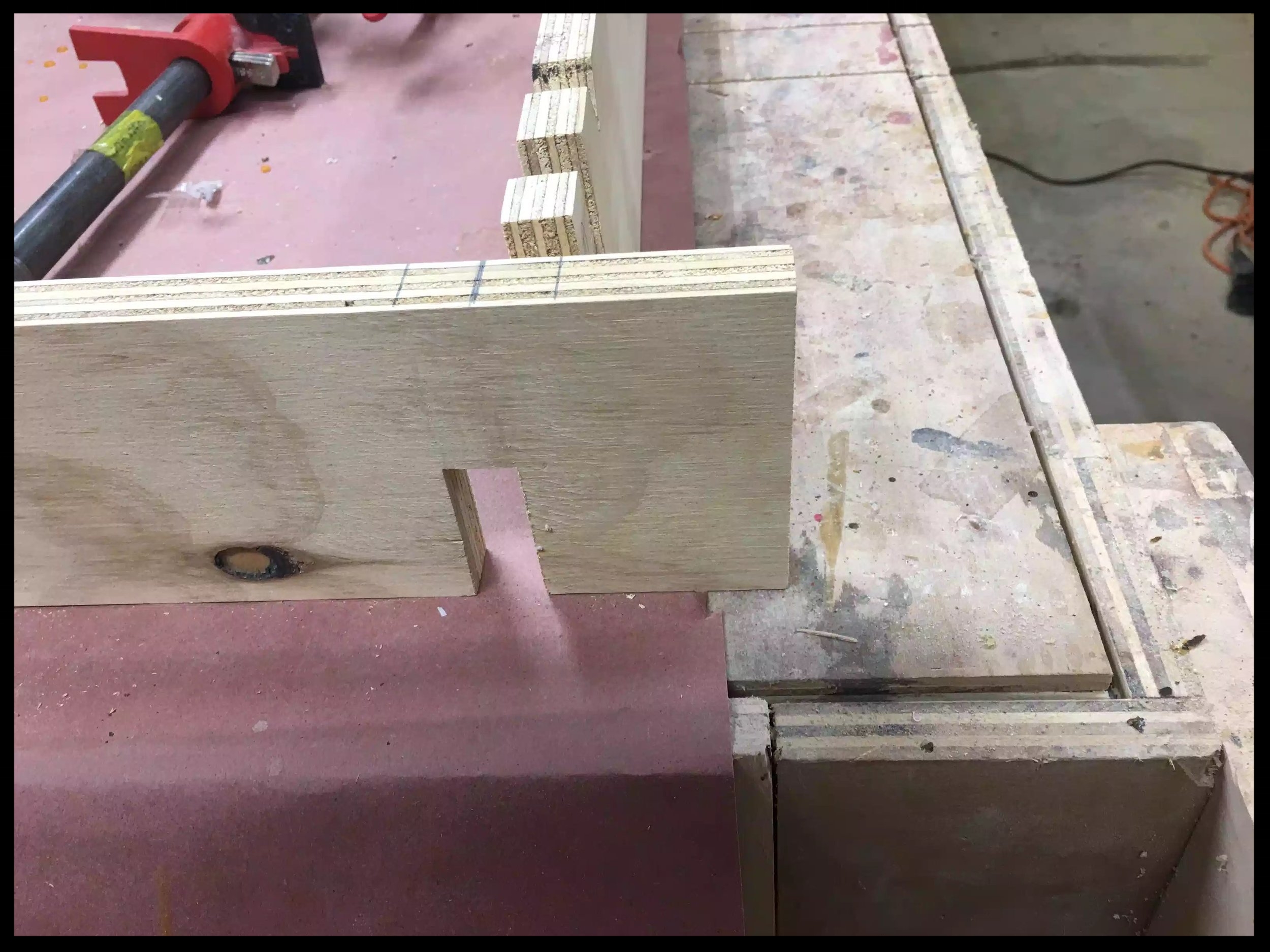
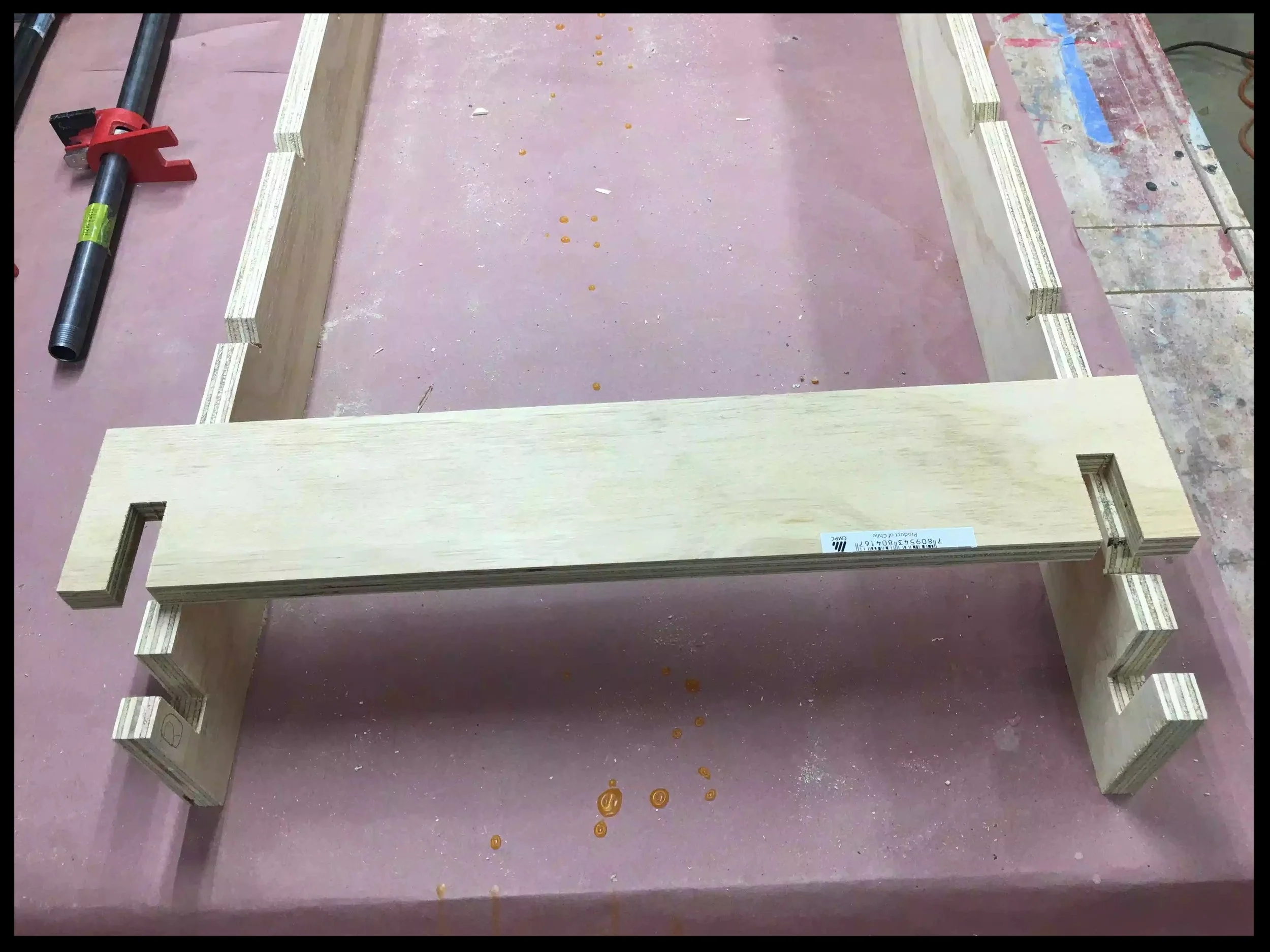
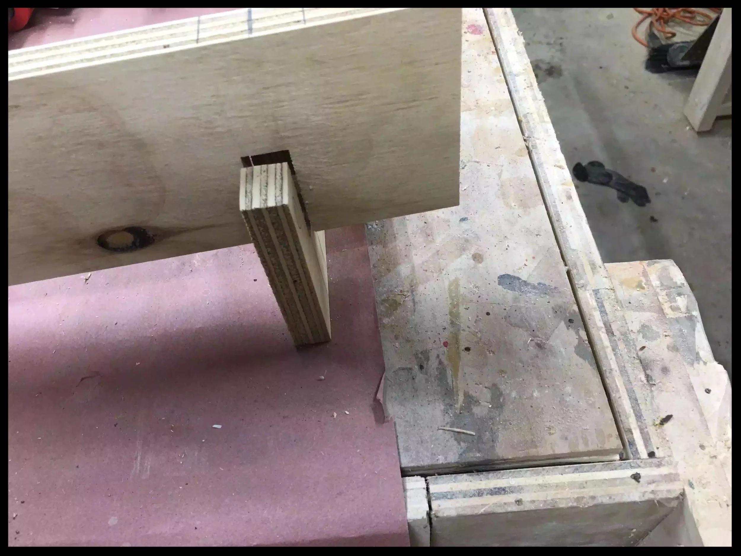
Added glue to the inside faces of the 4 frame parts
Assembled them in the clamping jig
Inserted all the pocket screws into their respective holes

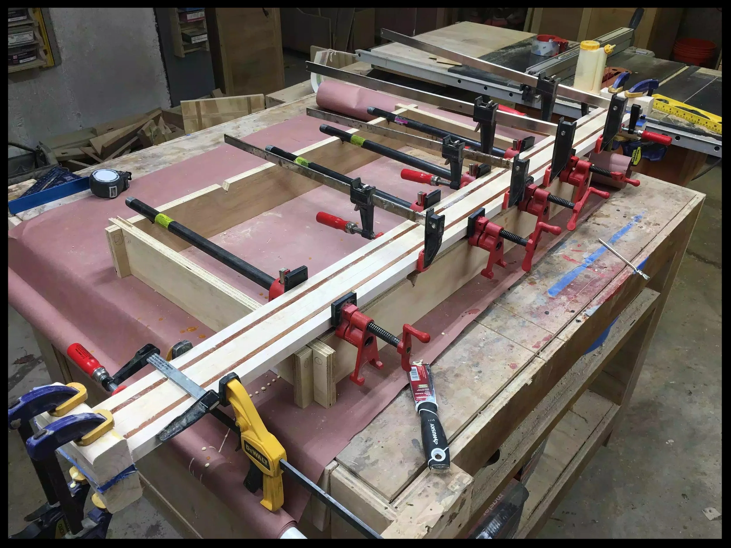
Here is the panel all set up in the pipe clamp jig, just about getting ready to screw them home. Glue has already been applied to the inside face of the frame pieces.

Here is another image of pipe clamp set-up I used the clamps because when using pocket holes they have the tendency to move the work-piece as you are screwing the pocket hole screws home, this set-up alleviates that.
ROUTER TIME 2.0
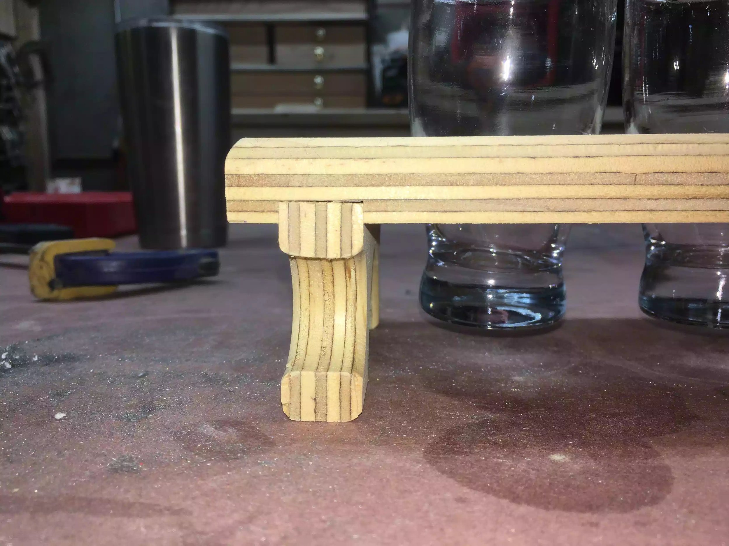
I also wanted to add a round-over to all the edges of the frame so that my son didnt hurt himself on the tray, so I took it over to my router table with a round-over bit in the router and did all the outside edges, then I used my palm held router to get the inside edges of the frame and it came out great but tomorrow I will be sanding it down to make it even smoother to the touch.

Here you can see the round-over profile on the outside and inside edges of the frame.
A LITTLE PAINT
I wanted to add some black paint to the carved out letters for my sons name so I used some I had on hand and let it dry over night as I will be applying a polyurethane coat tomorrow. I will be sanding this whole surface down tomorrow which hopefully will make his name pop on the tray.

Messy looking right now but I will clean it up tomorrow.
HOW I LEFT IT!!!
Below shows a picture of how I left the project today

Here is the project as I left it today, more finishing work tomorrow
NEXT
Sand the entire project
Apply the polyurethane prob 2-3 coats
Apply the Lego base-plates using Gorilla Glue