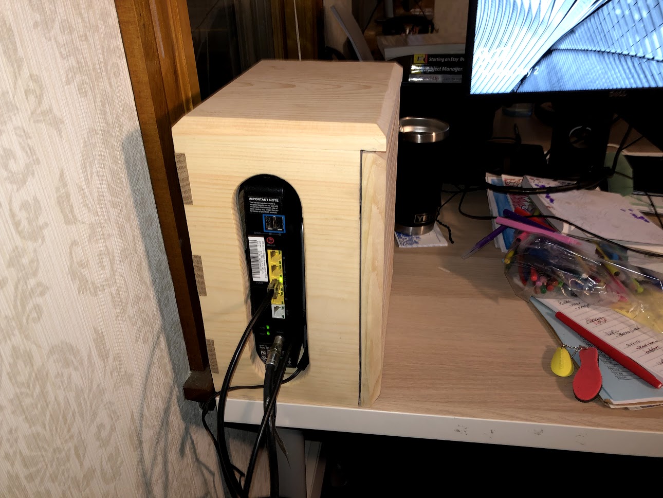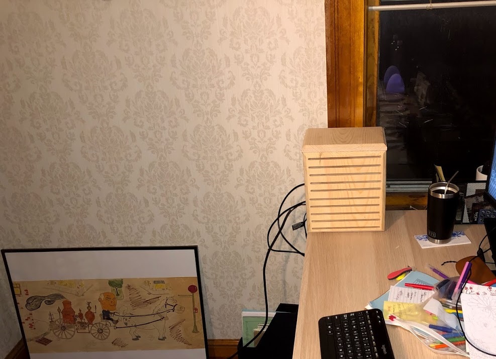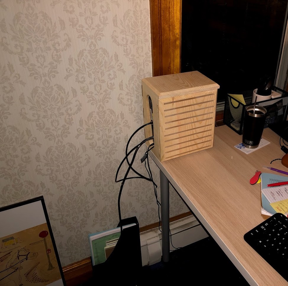


During the week I decided to re-organize the home office and in doing so needed to place the WIFI router box, but I didn’t have anywhere to really put it so I had to put the hideous looking box on the edge of one of the desks. So I decided to make a storage container to try and hide it in plain sight.
I didn’t really do much in the line of research on this but I did design it on my computer using Sketchup. I took the Router box’s dimensions and used them to come up with a storage box that I could store it in whilst stll sitting on the edge of the desk.
Here is how I made it:
Design
Materials Needed
The Parts
The Sides
The Base
The Back Slats
The Top
The Front Cover
All Finished
THE DESIGN
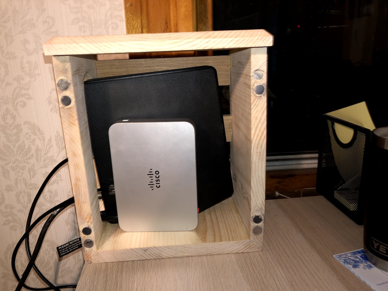
As I had mentioned I took the router box dimensions and used them to design what I wanted. The container is approx. 11” high x 6” wide x 9” deep. The joinery used to attach the base to the sides is a good old fashioned Tongue & Groove joint. The lid is held in place by 4 dowels that were inserted into the top edge of each side. The back slats have a half-lap joints into the back edges of the both sides of the box. The front is where it gets interesting, I designed a grill type front but because I need a way to access the router from time to time I am using magnets to keep it attached until I need to remove the lid.
I needed to make sure that the box had enough ventilation so as to let air moving around the WIFI box and that is why I placed a grill type front on the box. The left hand side has a oval shaped hole so as to let the wires and internet cable pass through the box to the router box.

Here you can see the 3D model of the storage box. The left hand side of the box has a big oval window so as that the wires can be fed through tp the router.
MATERIALS NEEDED
This project doesn’t require much in the line of wood in fact you could make it out some scrap wood if you any. I used most of my scrap so I needed to purchase the following
(1) 1” x 12” x 8’ of pine board and there will be decent of scrap wood left after you have completed the project.
(4) 1/4” wooden dowels
(8) 1/2” diameter magnets
Wood glue
Here is the length of 1” x 12” that I got at my big box store
THE PROJECT PARTS
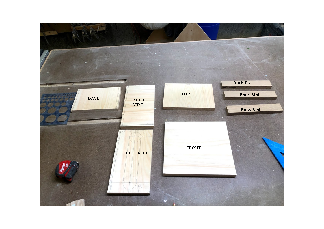
There are a total of 8 parts to making this storage box and they are, you can see the parts in the image below, as you can see they are not that big
Base
Left Side
Right Side
Top
(3) Back Slats
Font Cover
THE SIDES
Although there are 2 sides to this project there are some difference between them so I will start describing “The Left Side “ then move onto the right.
I decided to start with the left side as that was one of the pieces that needed the most work. The left side has an oval hole that is cut into it, and that is to allow the various wires to pass through the box into the router.
THE LEFT SIDE
STEP 1: LAYOUT
As you can see I did a decent amount of layout, The center marking are the dimensions for laying out the oval hole I want to cut out. The “X”s on the left side indicate where the back slats are going to be positioned with the half-lap joint later on.

STEP 2: REMOVING THE HOLES
Here you can see the left side on the drill press, the drill press has 2” diameter hole saw this is used to remove the hole which create the arc on the top and bottom of the oval hole that I want to create.


STEP 3: REMOVING THE WASTE
With both holes remove I can now use my jigsaw to remove the material left between both holes, this create the rough outline of the oval shape that I am looking for.

STEP 4: SANDING
With the material removed from the side it is time to clean up the inside edges of the oval hole and to that I used my Oscillating Spindle Sander to clean up all the very rough edges left by the jigsaw.

STEP 5: ROUND-OVER (Optional)
Although this step is optional I decided to use my palm router to add a round-over profile to the oval hole that I just made, I wanted this edge to be smooth because it will have wires going through there and I didn’t want them getting damaged. I also think it adds a nice touch to the project.

THE RIGHT SIDE
THE RIGHT SIDE
The right side is quick work mainly because There is no oval hole that we need to cut out as we did with the Left Side. Basically all that we needed to do was:
Cut is to size
Cut the groove in the bottom so as that we can mate it with the base later on.
We also need to remove the half lap grooves so as that the back slats can be mounted inside these grooves. But if you remember I did that already when doing the left side as I did them both together.

CUTTING THE HALF LAP JOINTS
Although there are a few difference between both sides, there is one common trait that they both have. They both need grooves cut on the back edges of the sides, this is so I can attach the half-lap back slats into them, these back slats are what help keep the little box together by joining both sides to each other.
WHAT IS A HALF LAP JOINT ?
A lap joint or overlap joint is a joint in which the members overlap. Lap joints can be used to join wood, plastic, or metal. A lap joint may be a full lap or half lap. ... In a half lap joint or halving joint, material is removed from both of the members so that the resulting joint is the thickness of the thickest member.

HOW DID I CUT THEM?
I cut the grooves out by doing the following:
I placed a 3/4” thick dado stack into my table-saw and raised the blade to 3/8” high
Then I placed my miter gauge on the table-saw and clamped both side pieces to the miter gauge fence.
Using my layout lines as guides I carefully remove the wood in both side pieces simultaneously this way I could guarantee that both side pieces would be the same.


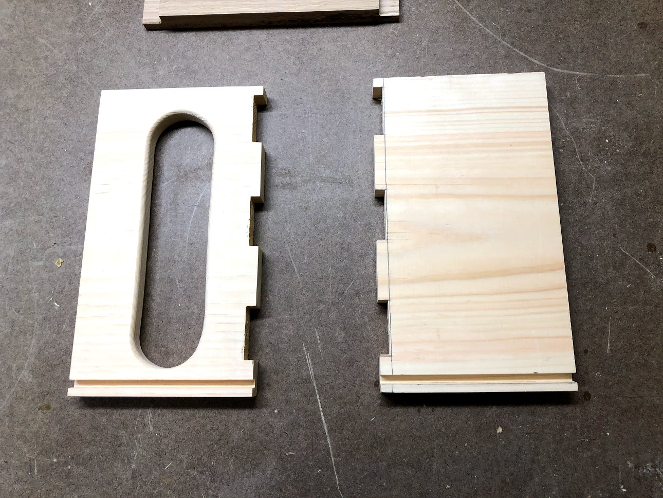
FINISHED GROVES
Here you can see both sides with the grooves or notches cut out, these notches are 3/8” thick as that is half the thickness of my 3/4” thick pine pieces and the oak back slats I will be attaching in these grooves.
THE BASE
CUTTING THE TONGUE’S
The base is also another board that will not take long in preparing, all I needed to do was to cut the mating tongues on the left and right sides of the base so as that they will mate into the grooves we already cut into the side pieces.
To cut the tongues on the base I installed a 3/8” wide dado stack into my table-saw and raised the blade up 1/4”, I also positioned the base 3/8” away from the fence and ran each side of the base through the blade and when you are done you will get a tongue that is 1/4” thick and also centered on the boards thickness.

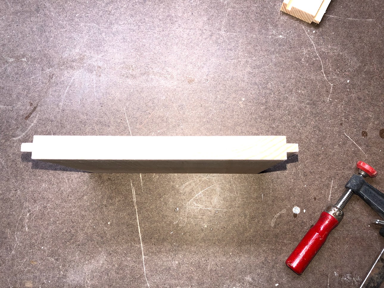
Here is a edge profile of the tongues that were into the base.
THE SIDES & BASE
Here you can see how the left & right sides will attach to the base, the grooves cut into the sides will fit into the tongue that was cut in the base. This is how the parts will be orientated in the final shape of the project.

THE BACK SLAT’S
The back slats are what join both sides of the box together, I didn’t want to place a solid wood back to the box as I wanted there to be a lot of ventilation within the box as it was a electronic component and air flow is necessary so as that it doesn’t overheat.
The 3 back slats are mounted to the WIFI storage box with a series of half-lap joints that I had already cut into the sides of the unit.
SKETCHUP PLAN VIEW
As you can see in the image there are 3 slats that I need for the box and all I need to do is to cut the other side of the half-lap into them. All this requires is that a rabbet is cut into the left and right side of each slat. Then I will glue and brad them into the sides of the unit.

TABLE-SAW : HALF LAP
In this image you can see one of the back slats on the table-saw, I have a 3/8” wide dado stack in the saw , raised to about 3/8” as that is half the thickness of my stock. I also used my miter gauge to back up the cut on its way through the blade to minimize tear out.

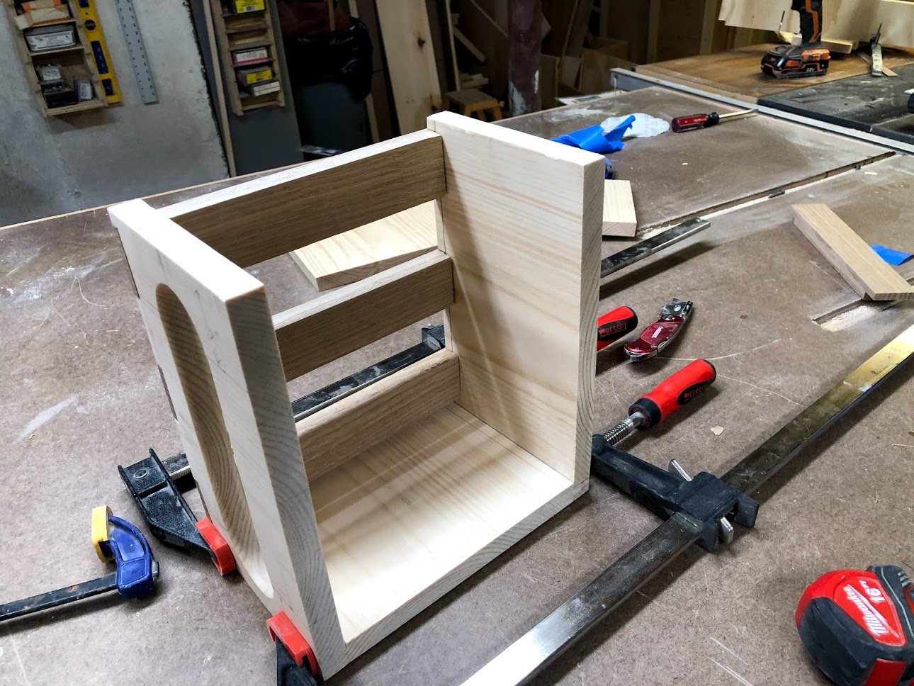
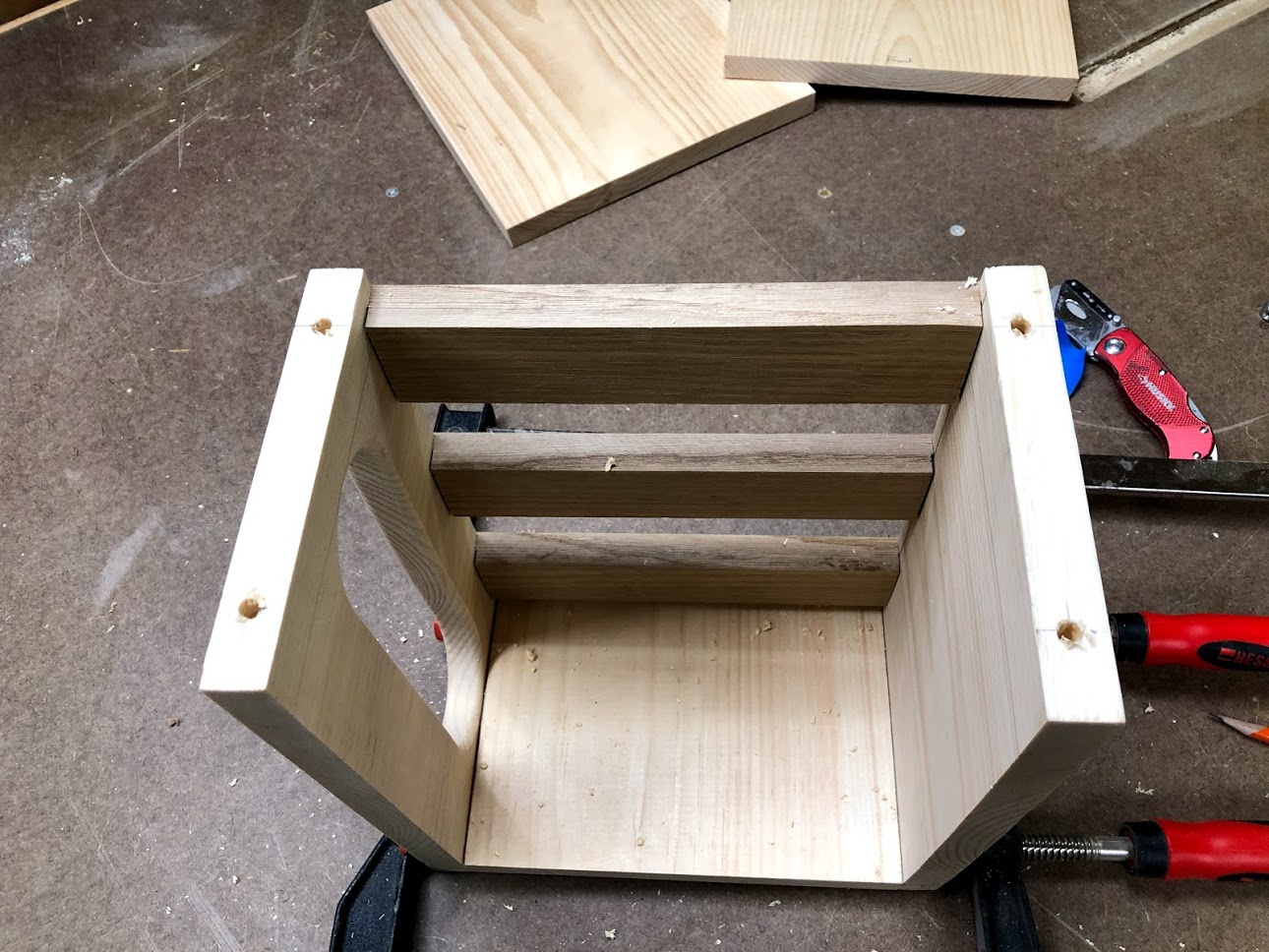
BACK SLATS DRY FIT
Here are the 3 back slats inserted into the unit, although my original plans called for the back slats to be made from the pine I found a little oak so I decided to use that instead, its nice to have a little contrasting wood in the back edge.
A SMALL GLUE-UP
Now that I had the sides, back slats and base all milled and more or less ready I decided to do a glue up of these components.
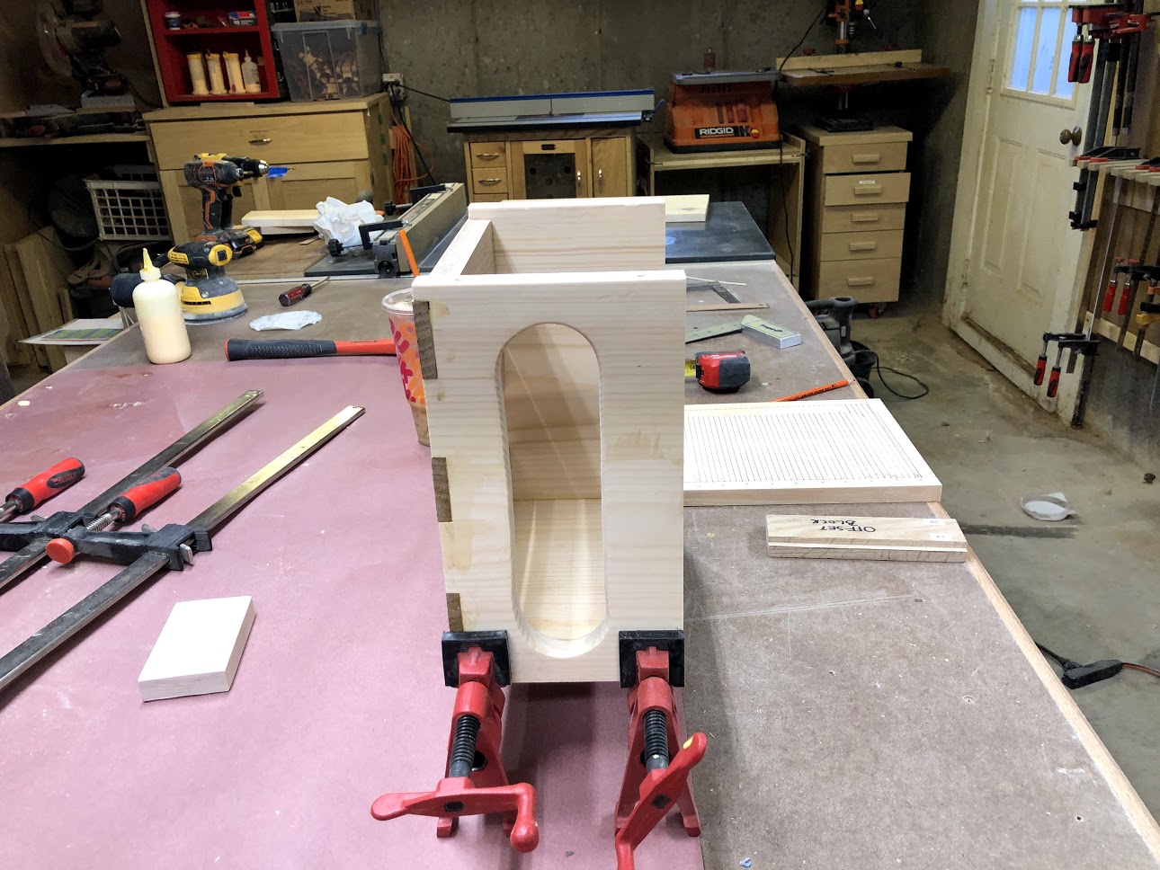
GLUE-UP THE SIDES & BASE
Since I had the base, sides and back slats ready I decided to glue them all together, there was still some work to be done on these parts but I needed the unit assembled to get certain dimensions before I could proceed.
The base is glued into the sides basically using glue, then I clamped them together.
The back slats were also glued into position but I needed to use a brad nailer to secure them in place while the glue dried.
THE TOP
The top was a straight forward process of preparing, I needed to do the following:
Cut the lid to size so as to fit across both the top edges of the side pieces.
Also wanted to add a chamfered router edge around the piece, this is purely for aesthetic reasons.
Finally I needed to add some 1/4” diameter holes, these were for the dowels I was going to use to attach them into the sides.
THE LID : BEFORE THE CHAMFER
Here is the piece of wood before I added them chamfer to all four edges.

CHAMFER APPLIED
Here is the top with the chamfer added to all four edges, I used a 45° chamfer bit in my router table to cut this, I think its a simple but nice profile.

DOWEL HOLES
In order to attach the lid to the sides I needed to predrill 4 holes, I used a 1/4” diameter forstner bit to do this.
GLUED IN THE DOWELS
I added the dowels and added glue into the holes and then finally added the holes to the underside of the lid and I was in business.

GLUE TOP ON
All that was left was to glue on the top and clamp it up, here you can see the clamps holding the top in place while the glue set, as you can see the top overhangs the sides by about 3/4” because I wanted the top to hide the end grain on the front panel once I attach that.


THE MAGNET RECESSES
Before I started working on making the front panel I wanted to get the magnet recesses out of the way, this was a simple enough process. The magnets are being inserted so as to attach the front panel in place, but I needed a way to attach and detach the front panel after all I needed to insert the router and if I ever needed to remove it I could just detach it, and this was the method I chose.
I needed to measure where I wanted to insert the magnet, 2 per side would be sufficient.
Then using my hand drill with a 1/2” forstner bit installed drill these holes, I drilled a hole to the depth of the magnet which was about 1/8” deep.
I added melted glue to the recesses with my glue gun and carefully orientated the magnets and stuck them in. After all I didn’t want the magnets to repel each other when they came into contact with each other, otherwise the front would not stay in place.
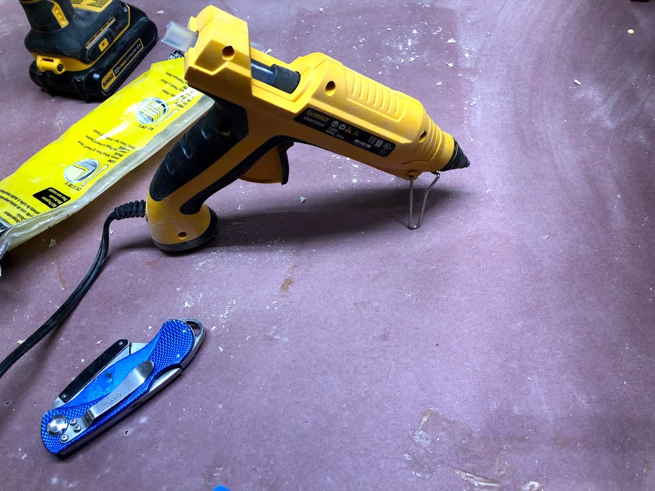
THE GLUE GUN
I though that I would show a quick image of the glue gun that I used, I don’t usually use this but I am glad that I have from time to time, its a quick and easy way of sticking two different materials together instead of mixing up epoxy.
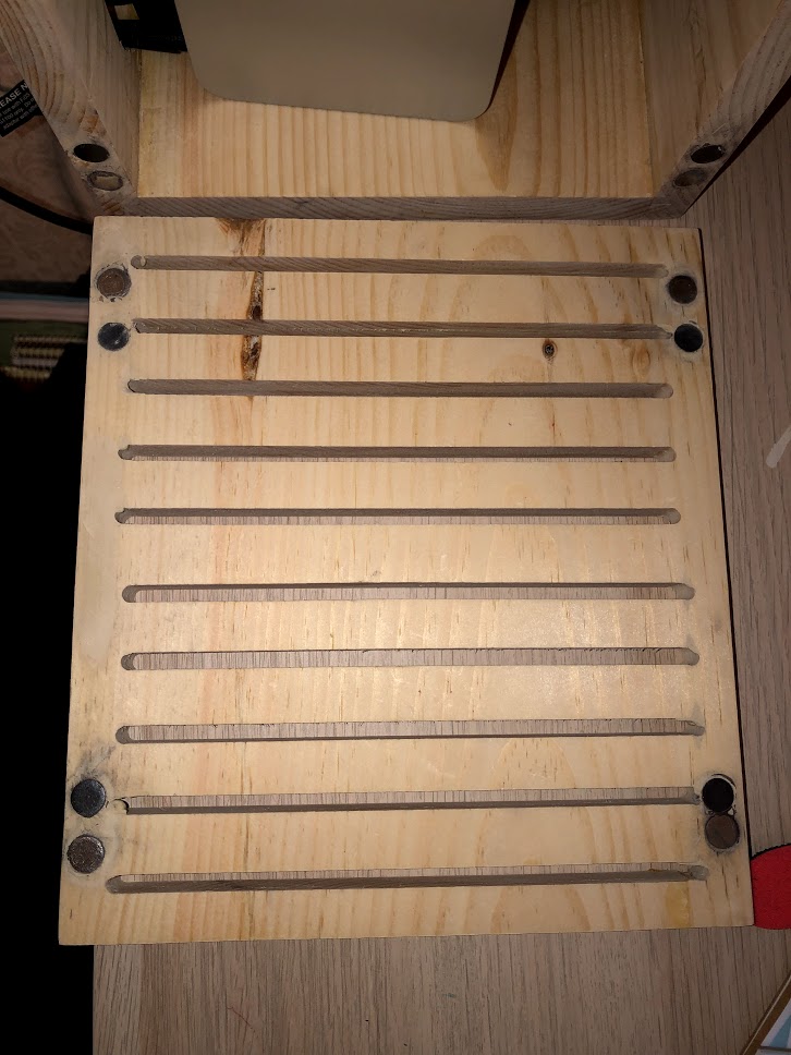
MAGNET RECESS’S
Here you can see the 4 recesses that I cut using my drill and a 1/2” forstner bit, where you position these into the sides is not that important but it is critical that you match these holes on the back face of the front otherwise the magnets will not interact and you will have a front panel that will never attach.

INSERT THE MAGNETS
All that was left to do was to apply the glue into the recesses and insert the magnets, although I don’t how it here but I made sure the magnet was orientated correctly by placing blue tape onto the face that would attract the mating magnet, then shove them into the glue and hold for a few seconds, it doesn’t take long for the glue to hold the magnets firmly in the sides.
I will need to do this same process in the back side of the front panel but I haven’t made that yet , but it is next.

THE FRONT PANEL
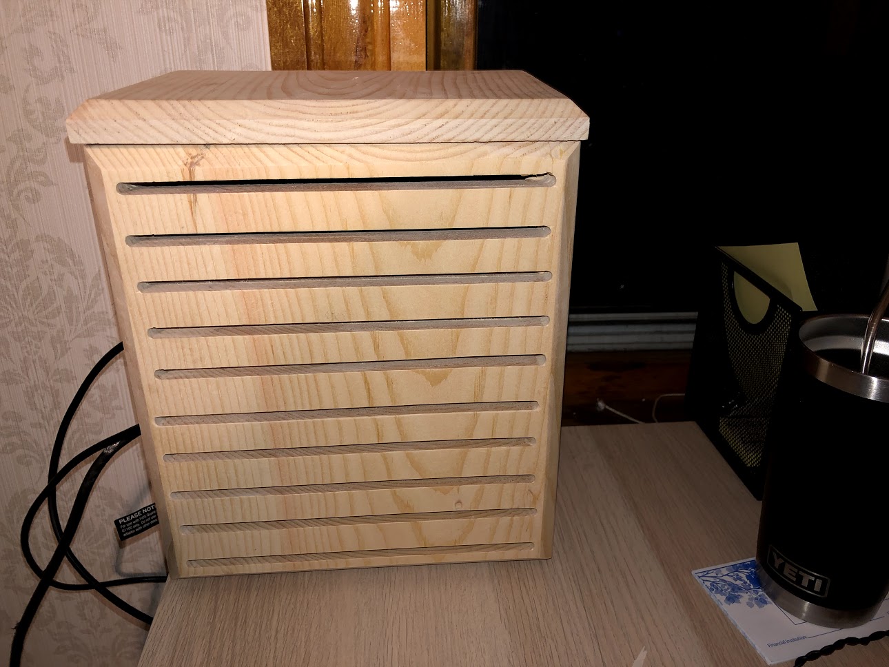
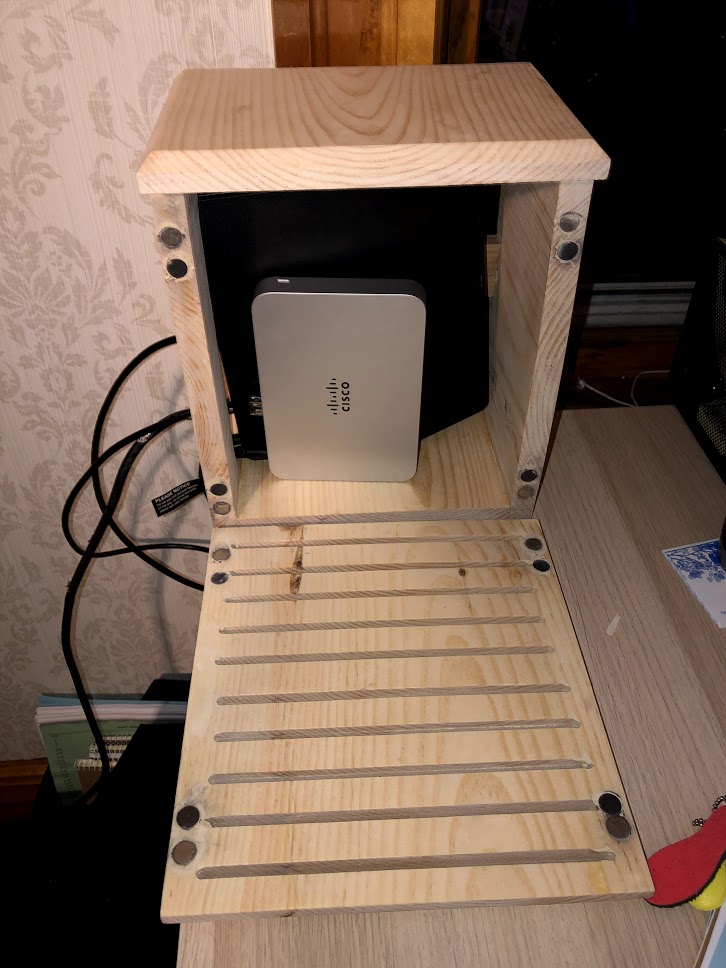
The front panel is basically the cover to the box and there is a lot of work in making it. Basically the front panel needs grooves cut into the front horizontally, these are through holes and they provide a decorative feature but they also add a ventilation solution. Electronic components tend to generate a lot of heat if they are contained inside of a storage compartment, these elongated holes solve that problem. I also added another chamfer to the outside edges of the front, thus making it blend in with the top. The last thing that I need to do is insert the magnets so as that they can attach the front to the magnets I had just placed into the sides.
CUTTING THE GROOVES
STEP 1: ROUTER TOP LAYOUT
The front panel has horizontal grooves cut into it. These grooves are what is called stopped grooves as they are cut into the inside edges of the panel and don’t break any edges. In order to do this I needed to insert a 1/4” router bit, but I also needed to know where the bit starts and stops it cut. So in this image I used a T-square to strike lines on the blue tape that shows where these router starts and stops it cuts.
These 2 lines are pivotal to starting and stopping the workpiece in the right locations because if I didn’t have any reference lines the grooves would not be aligned with each other.


STEP 2: LAYOUT MARKS
As you can see the workpiece is sitting on the router table top, the blue tape has 2 lines which are a 1/4” away from each other which is the dimeter of the router bit in the table, the line on the left marks the insert point where I need to drop the workpiece on to and start the cut, the workpiece also has a line on each end of the workpiece, this is also the start and stop point and when the lines intersect the marks on the blue tape I know that the grooves are cut in the right place.

STEP 3: START CUTTING
There are a few things that I want to show you with the workpiece, the first is on the left hand side a series of lines that I drew in pencil, these lines mark the locations of where I want the grooves to be located, the other thing that I wanted to show was how I orientated the board as to how I cut it, I located each groove of equal distance so I cut the top groove first and then the bottom groove 2nd, all while maintaining the fence on the router table in the same location and as you can see the start and end locations of each of the grooves are more or less the same length and match each other in length.

TIP: Since the thickness of wood is 3/4” thick I made several passes with the router bit to remove the wood inside the grooves.
MORE CUTTING (4/10)
There are 10 grooves in total to be cut onto this board and all are cut the exact same way, I number the grooves sequentially on the board , I know that the numbers are faint but they re along the left edge of the board. Basically after every groove is cut I rotate the board 180° and make another cut, this way I will only need to adjust the fence on the router table 5 times instead of 10.
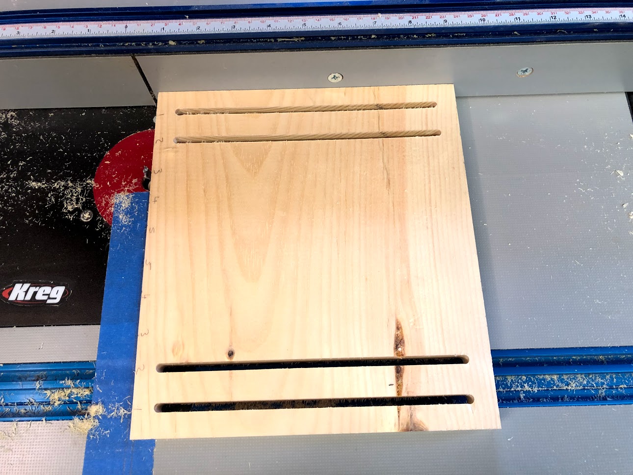
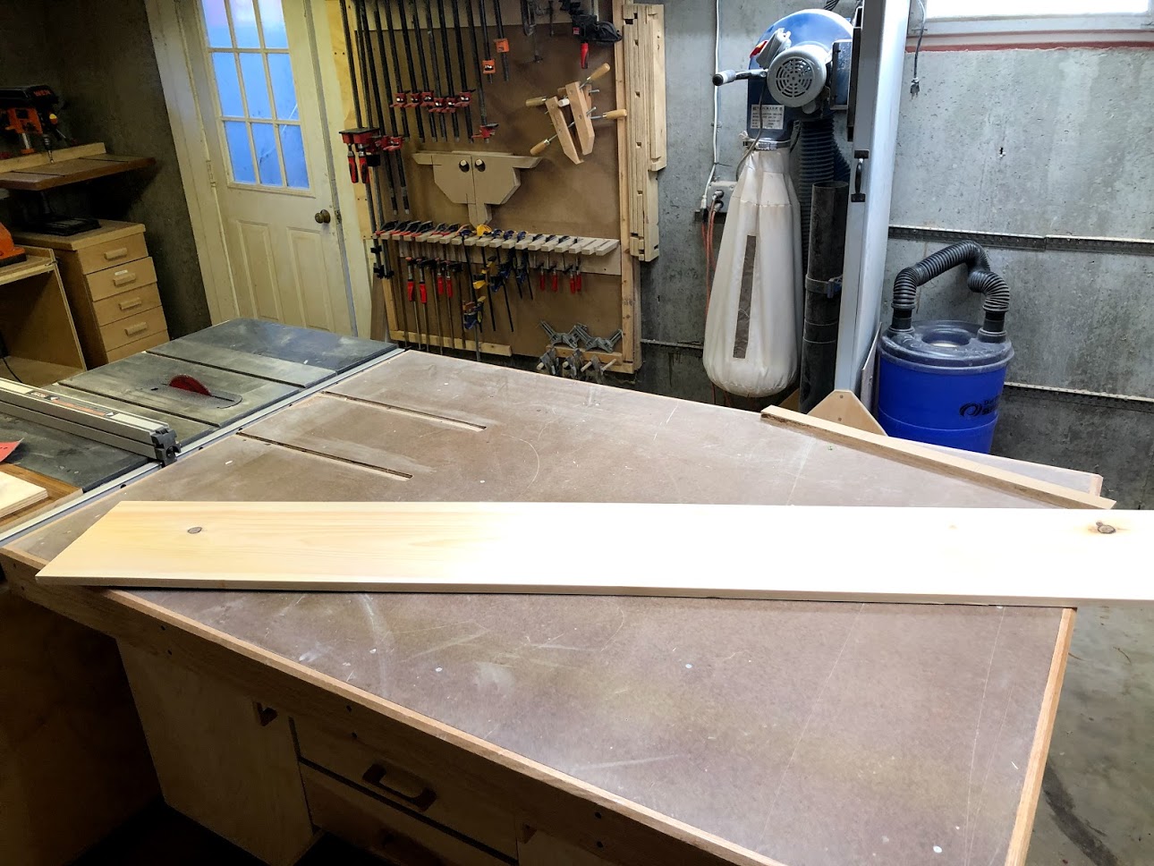
GROOVES ALL COMPLETE
Here is the front panel with all the grooves cut into it, it came out ok but I do have a few grooves a fraction out of place but I am ok with that.

ADDED A CHAMFER
Although this is an optional additional, I thought it would look good to add a chamfer to all 4 edges of the front panel, as it would help to blend the front panel with the top of the unit. did this over at the router table with the same chamfer bit and set-up I used for the top.

ADDING THE MAGNETS
All that I needed to do now was to add the magnets to the inside face of the front panel. If you remember I added the magnets already to the side parts of the unit earlier in the project, now I needed to complete this process as the magnets would be used to attach the front panel to the unit.
BUT I HAD A PROBLEM!!!!
The magnets that I inserted into the sides and front panel were not strong enough, I used what are called Ceramic magnets and when I attached the front panel to the unit and even though I put the magnets in the right locations they were not strong enough.
So to remedy the problem I did some research and it turns out that although ceramic magnets are used for a variety of tasks there holding power is not as strong as that of a rare earth magnet, so that is how I remedied this little problem, I went to my big box store and bought 8 of them, but now there are 8 magnets in the sides of the unit and another 8 in the front panel, which doesn’t look the best but but it did work.
A LITTLE LAYOUT
Here you can see the back face of the front panel, I needed to layout the locations of where to place the magnets so as that they matched up with the magnets I had already installed into the sides of the unit. The process was the same I used a 1/2” diameter forstner bit in my drill to drill out the recess then used my glue gun to attach the magnets into the wood. I needed to be careful so as to orient the magnets that they didn’t repel each other when they met.
All this was done before I realized that the magnets were not strong enough, so the next phase of the project was to install the rare earth magnets and that will be next.

MORE MAGNETS
As I had mentioned earlier the ceramic magnets that I had installed earlier were not strong enough so I needed add 8 more magnets to the case and front, so I used Rare Earth Magnets and the did the trick. I know that the front panel and the units look a little messy and that is because when I was sanding the edges the black residue came off the ceramic magnets and dirtied up the unit a little, but to be honest I tried cleaning it off. Anyway the inside of the unit will never be seen.

ALL FINISHED