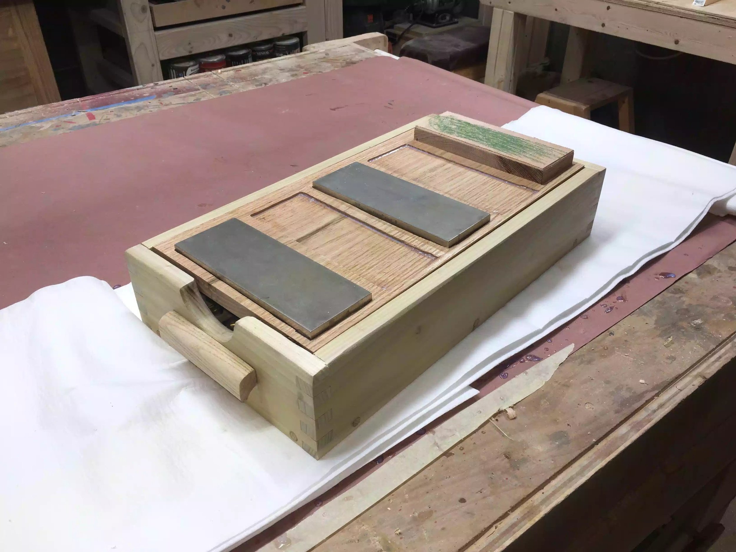
Sharpening station

Project Award : Portable Sharpening Station

badge-daily-top-3.png

I recently received an award for the Portable Sharpening Station from www.lumberjocks.com

If you would like to read all the project from beginning to end, I created a blog series that can be found here. If you like the project that much I have just made plans available for the project here.

Thanks Lumberjocks for supporting everything that I do, and I am always appreciative of any and all recognition that I receive.

 
Click for details: Sharpening Station
The completed Sharpening station.

The completed Sharpening station.


Portable Sharpening Station : All Finished

Today I finally got to finishing this project all I needed to do was to add wooden plugs to the countersunk screw holes for the base and apply a urethane finish to the entire sharpening station.

MADE THE WOODEN PLUGS

I usually have some oak dowels lying around the shop but for the life of me couldn’t find any so I needed to make my own which is very easy. I used a 3/8” plug cutter in my drill press and since I had some oak scraps lying around from this project I used it. Below you can see some pictures of the process.

Step 1 : Cut the plugs on the drill press

Step 2. Added some glue and hammered the plugs into place

Step 3. Was to flush cut the plugs to the surface.

Cutting the plugs on the drill press.

Cutting the plugs on the drill press.

Here is a close up of the plug cutter.

Here is a close up of the plug cutter.

Here is the protruding plugs that needed to be flush cut.

Here is the protruding plugs that needed to be flush cut.

Finally using my flush cutting saw, I trimmed the excess off.

Finally using my flush cutting saw, I trimmed the excess off.

APPLYING THE FINISH

Now that everything was done all that was left was to apply a finish, the finish I wanted to use was Minwax Poly-Crylic but by big box store didn’t have any so I choose an alternative water base polyurethane and I applied 3 coats.


Here is the last of the 3 coats, applied to the top, still wet.

Here is the last of the 3 coats, applied to the top, still wet.

Here is a before picture , this is before I applied the finish.

Here is a before picture , this is before I applied the finish.

This is after the finish has been applied, I love how the box joints pop.

This is after the finish has been applied, I love how the box joints pop.

ALL FINISHED

All that is needed now is to wait for the finish to dry, but here are some final pictures. I love how handy this station will be and I should have made it a long time ago, everything that I need to sharpen my tools is now in one place just the way I like it.

This concludes my blog on this project, I hope you have enjoyed reading about this project as I have enjoyed making it. I will be releasing plans for this in my shop as soon as I have a chance in putting them together.

Until the next time I’ll catch you later.

This station is a very comfortable height for me to work on, although I might have gone over-board in its design it is extremely functional.

This station is a very comfortable height for me to work on, although I might have gone over-board in its design it is extremely functional.

Here is my Veritas MKII honing jig being put to good use.

Here is my Veritas MKII honing jig being put to good use.

I really like the contrasting oak plugs that I used and also really enjoyed making the pulls, which I made from solid ash.

I really like the contrasting oak plugs that I used and also really enjoyed making the pulls, which I made from solid ash.

I really love having everything that I need right at my finger tips.

I really love having everything that I need right at my finger tips.

Portable Sharpening Station: Day IV

So today I got so much done and the project is almost finished all I have to do is apply a finish to the station and add wood plugs to the screw holes and it will be ready.

Here is what I got done today:

  • Made a leather strop

  • Remade the base

  • Made wooden pulls

MADE A LEATHER STROP

One final item that I needed to make for the sharpening station was a leather honing strop and I found a YouTube video that Paul Sellers made regarding making one, he used a scrap piece of wood and some leather that I purchased at Woodcraft.

Since I had some oak left over from the lid what better use for it than to make 2 leather strops, I cut the oak to the same size as that of the diamond sharpening stones, 8”x3” and I used double sided tape to adhere the leather to the oak.

Here is the honing leather and honing compound that I used, you can find more details on woodcraft, just click the links. But here is all the materials I needed to make the strop’s.

Here is the honing leather and honing compound that I used, you can find more details on woodcraft, just click the links. But here is all the materials I needed to make the strop’s.

Here are the 2 pieces of oak that I used for the base of the strop.

Here are the 2 pieces of oak that I used for the base of the strop.

Next I cut the leather to size using a box cutter.

Next I cut the leather to size using a box cutter.

I added the double sided tape.

I added the double sided tape.

Now I have 2 nice honing strops and it only took 5 minutes.

Now I have 2 nice honing strops and it only took 5 minutes.

REMADE THE BASE

When I was looking at the base I needed to make one recess for a different type of honing guide, I really didn’t like the look of the recesses that I made previously so I just remade the base and added the extra recess. You can see the pictures below, I remade the base the same way by drawing layout lines of the size of the recesses that I need, used my palm router to route to the line and then cleaned it up with some chisels and now it looks much better.

Here is the new base with the added recess for an eclipse stile honing guide.

Here is the new base with the added recess for an eclipse stile honing guide.

Here is the new base installed and looks a lot better,

Here is the new base installed and looks a lot better,

So here is most of my accessories in the box, still need to figure out a method for housing my diamond plates.

So here is most of my accessories in the box, still need to figure out a method for housing my diamond plates.

MADE HANDLES

I needed to make 2 handles for the sides in order for me to carry the station around easily as it is heavy.

I originally made these pulls before for my Drill press cabinet that I made, I designed the pull on Sketchup and then made a bunch of them when I was making the drill press cart, and of course as usual I couldn’t find them, so I needed to make some more.

I had some left over ash from the drill press project that I used and made like 6 handles out of 30 inch piece of ash.

I used 3 router bits in making them, 1/2” Cove bit, 1/2” round-over bit and finally a 1/4” round-over bit. You can see the pictures below. I also attached my original project where I went into more detail on how I made the pulls, check below.

Here is my ash blank, I started off the process by routing the cove on the back side of the handle.

Here is my ash blank, I started off the process by routing the cove on the back side of the handle.

I made several passes with the cove bit, raising the bit incrementally.

I made several passes with the cove bit, raising the bit incrementally.

Here are the 3 bits that I used firstly on the left is a 1/2” cove bit, middle 1/2” round-over, right is a 1/4” round-over.

Here are the 3 bits that I used firstly on the left is a 1/2” cove bit, middle 1/2” round-over, right is a 1/4” round-over.

I finally used the 1/2” round-over to add a profile to the top of the handle and then used the 1/4” round-over  to the pull.

I finally used the 1/2” round-over to add a profile to the top of the handle and then used the 1/4” round-over to the pull.

Here is a layout of what router bits and where I used them.

Here is a layout of what router bits and where I used them.

So here are the 6 pulls that I made from that one piece of ash, its so much cheaper doing your own pulls and are totally customizable

So here are the 6 pulls that I made from that one piece of ash, its so much cheaper doing your own pulls and are totally customizable

All that was left was to secure them on to the sharpening station, all I did to attach them was to center the pull on the center of the sides pre-drilled 2 holes to receive screws into the handles

Here is the pull attached.

Here is the pull attached.

So the project is almost complete and all I need to do tomorrow is to start applying the polyurethane finish and adding some wooden plugs to cover up the screw holes located near the bottom.

Below is where I left the project today and took several pictures to display it.

The sharpening station is more or less finished, I need to purchase 1 or 2 more sharpening stones .

The sharpening station is more or less finished, I need to purchase 1 or 2 more sharpening stones .

Here is a frontal shot

Here is a frontal shot

Here is the inside

Here is the inside

Other than the blemish in the recess I think it looks great, its only a shop project so it will get dinged up for sure and wont look any better than this in a short amount of time.

Other than the blemish in the recess I think it looks great, its only a shop project so it will get dinged up for sure and wont look any better than this in a short amount of time.

NEXT

  • Need to add wooden plugs to cover up the screw holes, Ill probably use oak.

  • Finally I need to start applying the finish, probably 2/3 coats of Polyurethane.

Thanks for looking, catch you soon.

Portable Sharpening Station: Day III

Today was all about the recesses that I needed to create for the sharpening stones and to be honest there was a decent amount of layout work to be done and maybe 20 minutes of me actually using my router. I gone to great detail explaining the how and the why of the steps that I took.

  • Materials Needed

  • Laying out the measurements for the template

  • Drill Press

  • Template Cut-outs

  • Dry run

  • Router time.

  • Recesses all done

MATERIALS NEEDED

I decided to use 1/2” thick MDF (Medium Density Fiberboard) for the template because of a couple of reasons, its very flat and easy to mill. I went to my local Big Box store and purchased a 2’x2’ project panel and cut it down to the size I needed.

Here is the project panel cut to size, before I made all my layout lines

Here is the project panel cut to size, before I made all my layout lines

MEASUREMENT LAYOUT

The longest part of this whole part of the project was this section, laying out all the lines and determining how much offset I needed in making the template, because if you remeber I am going to be using a router template bushing to guide the router inside the template giving me my final shape.

Here are some of my measurements that I am using for the template, but if you are going to make your own your measurements are probably and most likely going to be different than mine because I am using Diamond sharpening stones that are 8” x 3”. One more thing that I want to make you aware of I decided to make the template the actual size of the entire surface area of the sharpening station as it gave me more room to apply double sided tape to fix it to my tray that I will be applying the recesses into.

  • I maintained a 3/4” wide space around the perimeter of the MDF template as this represented the box beneath

  • Next to that line I came in an additional 1/2” and maintained that spacing between each of the stones and maintained this spacing all the way across the template so as that the spacing between the sides of the sharpening stones were consistent.

  • On the front edge of the template I measured 3/8” in from the first line I drew which was 3/4”.

  • One other reminder because I am a guide template bushing I needed to add 1/4” to the template to account for the offset.

  • Below you can see the measurements on the actual template.

Here is a picture describing all the measurement descriptions I gave above.

Here is a picture describing all the measurement descriptions I gave above.

DRILL PRESS

I needed to drill relief holes in the template because I will be using a jigsaw and because all the cutout are on the inside of the template I needed an entry and exit points for the jigsaw bit. So I used a 1/4” brad point drill bit so as that I could register the bigger bit because I really needed to stay inside my layout lines. I then came back with a 1/2” brad point to finish cutting all the holes, I put 1 hole on each corner of where the recesses will be cut out.

Here is an image after I used the 1/4” brad point drill bit.

Here is an image after I used the 1/4” brad point drill bit.

Here is the template after I added the 1/2” holes.

Here is the template after I added the 1/2” holes.

Here is the drill press in action drilling out the 1/2” holes, this diameter bit has just enough room for me to fit my jigsaw blade through.

Here is the drill press in action drilling out the 1/2” holes, this diameter bit has just enough room for me to fit my jigsaw blade through.

TEMPLATE CUT-OUTS

I needed to remove 5 sections of the template and to be honest there was not much to see except me using a jigsaw and dust flying everywhere, always remember to use eye protection and I always use a respiration mask to stop me inhaling he MDF dust as there is a connection with that dust and cancer.

Here is the template almost complete I needed to do a little sanding to even out the jigsaw blade marks, I also needed to square off the corners.

Here is the template almost complete I needed to do a little sanding to even out the jigsaw blade marks, I also needed to square off the corners.

TEMPLATE DRY RUN

Before I used the template on the solid oak top I decided to use it on a scrap piece of plywood so as that if I needed to fine tune the template I could do it before I started actually routing the recesses.

Here is the template on the scrap piece of plywood after using it, I needed to fine tune the template before using it on the oak.

Here is the template on the scrap piece of plywood after using it, I needed to fine tune the template before using it on the oak.

Here is the dry run on the plywood, not too bad for my first time using a template.

Here is the dry run on the plywood, not too bad for my first time using a template.

USING THE TEMPLATE

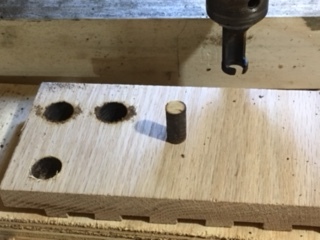
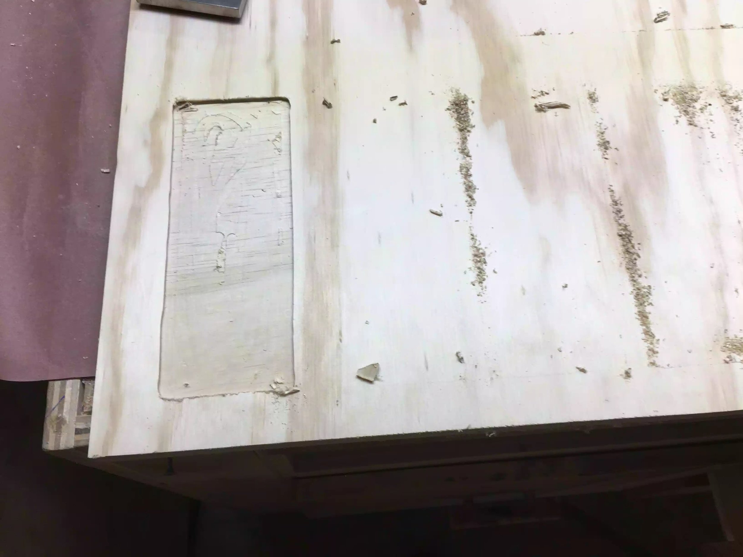
Next was to actually use the template to route the 5 recesses that I needed for the stones. When it came to deciding the bit style I wanted to use the 1/4” spiral bit but when it came to putting the bit into the router I realized that the bit was not long enough to protrude through the guide bushing, so I moved the bit a little more out of the Colette, enough so as that I went deep enough through the template and into the work-piece, the problem with that was that while I was routing the recess the bit moved out more probably because the Colette didn’t hold the bit in place and it dug deeper into the oak panel.

So I needed to come up with a plan b and that was to use 1/2” straight bit with a 3/4” OD bushing that way I could keep the template dimensions the same and still receive the exact dimensions that I needed to fit the diamond plates and it worked. The only problem was that I didn’t go as deep to get rid off the marks left from the spiral but slipping. In woodworking sometimes you face these issues and you need to find solutions to them, although I was plenty mad at the bit slipping , it was my fault that it happened and I will not be doing that again. To rectify this problem in the future I need to make sure that I have the correct size bit for the operation that I have before I actually start doing the work, a simple solution would be to purchase a router bit extension piece.

To be honest I thought about not writing about this, but woodworking has thought me to own up to mistakes because everyone makes them even the pros and mistakes make you think outside the box when trying to rectify them, at the end of the day I still achieved what I was looking for.

Here is a picture of the template on the oak work-piece, I used double-side tape to secure the template to the oak top.

Here is a picture of the template on the oak work-piece, I used double-side tape to secure the template to the oak top.

RECESSES ALL COMPLETE

Here are a few pictures of the finished top, you can see the stones in place, I only have 2 diamond stones right now and I need to get at least one more, I will be putting a leather strop pad on the last recesss for finishing up my sharpening process, but that comes tomorrow.

Here are 2 stones sitting in the recesses , they fit great and will not be moving around.

Here are 2 stones sitting in the recesses , they fit great and will not be moving around.

Here is the front of the sharpening station, I was thinking off adding finger pull holes to remove the sharpening stones but they are not so deep that I cant just lift them out of the recess.

Here is the front of the sharpening station, I was thinking off adding finger pull holes to remove the sharpening stones but they are not so deep that I cant just lift them out of the recess.

Here is aside view, as you can see the finger holes are deep enough to pull out the top when I need to have access to the box contents.

Here is aside view, as you can see the finger holes are deep enough to pull out the top when I need to have access to the box contents.

Well that is all I had time for today,

NEXT

  • Make a leather strop pad for the last recess, I have the leather, just need to figure out a way to add some thickness and rigidity to it.

  • Fill the screw holes with wooden plugs

  • Apply a finish to the station.

Portable Sharpening Station: Day II

I returned to the project today after the weekend and I had the following steps to do.

  • Sand down the box frame after the glue-up

  • Make & Install the base

  • Cut the top to its final dimensions

  • Add some round-overs

SANDING

The glue had set and I think I used a bit too much as the squeeze out was on the excessive side, so I took my random orbital sander and went through 120 - 220 grit sandpaper to clean it up. The finger joints look OK there was a few tiny spaces in between the fingers but I will need to fill them in later.

Anytime I get inconsistent spacing between joinery methods I usually use the saw dust and glue trick. All this is is the mixing of a little glue and sawdust from the same species of wood I use for a project in this case is poplar and rub it into the spacing let the glue set for about 30 minutes and then return to sand it down and magically the gaps disappear. I will do this towards the end of the project.

This picture shows the state of the piece after removing the clamps but before sanding it down.

This picture shows the state of the piece after removing the clamps but before sanding it down.

Here is the box after sanding, need to fill in some little gaps around the finger joints but other than that it looks fine.

Here is the box after sanding, need to fill in some little gaps around the finger joints but other than that it looks fine.

THE BASE

The base is nothing special , I am using a piece of 3/4” plywood as it will not be seen and then using the counter-sunk holes I already made around the bottom of the box parts I will use 1-1/4” screws to secure the base. I am not gluing it just in case I need to replace it in the future. I also needed to resolve a problem with keeping tools and accessories in position in the box an not be bumping into each other and possibly damaging them. To solve this issue I decided create a recess for the accessories I will be storing in the box, so I used my palm router and free handed the recesses to hold the tools. I will be using a similar process for the top but that is a much more precise recess and I will need to adapt the process whilst still using the router.

I used this scrap piece of 3/4” plywood for the base. I am cutting it down to final dimensions here on the table-saw.

I used this scrap piece of 3/4” plywood for the base. I am cutting it down to final dimensions here on the table-saw.

I am layout out the lines so as that the honing guide sits inside and will not rattle around.

I am layout out the lines so as that the honing guide sits inside and will not rattle around.

I used my palm router to remove the bulk of the recess and then went back with my chisel and mallet to clean up the edges.

I used my palm router to remove the bulk of the recess and then went back with my chisel and mallet to clean up the edges.

Here is the honing guide accessories all nice and snug, Ill leave it for now and can always remove the base when I need to add more recesses for other tools. I still need to figure out how to store my sharpening stones in the box cavity when its not…

Here is the honing guide accessories all nice and snug, Ill leave it for now and can always remove the base when I need to add more recesses for other tools. I still need to figure out how to store my sharpening stones in the box cavity when its not in use.

Another view of the base, before its secured to the frame.

Another view of the base, before its secured to the frame.

Base is all secured and looks functional.

Base is all secured and looks functional.

THE TOP

I am starting work on the top today but will need to finish it tomorrow. The top has a decent amount of work to do because it houses all my sharpening stones, I am creating recesses in the solid oak top so as that when I am using the sharpening station my stones stay stationary. To achieve this I need to use my plunge router together with a template that I need to make, I also need to use a template guide bushing on my router so as that I remove the precise amount of material for the stones to fit in, I purchased the Bosch bushing pack for my Bosch router which is the 1617 plunge router.

I will need to do a little more research on how to use a template for routing as I have never done it before. What I have so far I will show later.

TEMPLATE ROUTING

As you can see from my 3D rendering of the project below the top is to receive 5 recessed sections for the stones and a stropping plate.

3D rendering of the sharpening station.

3D rendering of the sharpening station.

USING TEMPLATES TO ROUTE RECESS

After researching online for a little while I found that I needed a couple of things before I could do this recess in the top. I needed to figure out the following:

  • Do I need tools that I don’t have for this task?

  • Do I need to make a jig of sorts?

  • Measurement considerations?

DO I NEED TOOLS?

After researching I found that I needed to buy a template bushing set for my router, a bushing is a router accessory that can be used with a jig, lettering, inlay work, even reproducing furniture parts. Here's the basic concept: A guide bushing mounts to the router's sub-base with a tube that protrudes below. A straight router bit extends through the tube. The outer surface of the tube rides against an edge guide or template, keeping the bit a set distance (offset) from the edge guide or template, see picture below.

Here is a picture that I found online to show the bushing in the router.

Here is a picture that I found online to show the bushing in the router.

In the marketplace you'll find two bushing styles. The Porter-Cable two-piece (shown below) uses a screw-on locking ring to hold the tube part to the router base. This style fits a wide range of models. The other style of guide bushing clicks into place, but only fits Bosch routers. If your router doesn't accept these common styles of guide bushings, consider buying adapters and sub-bases .

The style of bushing I needed was the one pictured on the right below.

WD321491.jpg

DO I NEED TO MAKE A JIG?

I don’t necessarily need a jig of sorts but I do need to make a template. A template is guide that I will use in conjunction with the guide bushing so as to guide the router to the shape that I need to create. I have decided to make the template because I have quite a lot of milling to do as I need to create 5 recesses and to do that free hand would be extremely difficult and would also mean a lot of clean-up when I was done with the router. Using a template negates all that clean-up probably with a chisel and also provides nice clean edges in less time.

I need to figure out how to make the template, that is tomorrow!!

Here is my router and bushing set.

Here is my router and bushing set.

MEASURING OFFSETS

To figure the offset, measure the outside diameter (OD) of the guide bushing tube and subtract the diameter of the bit. Next, divide this figure by 2 to determine the offset. In the example at below subtract the 1⁄2 " bit diameter from the bushing's 3⁄4 " OD. You get 1⁄4 ". Now divide this number by two and you arrive at a 1⁄8 " offset.

This diagram can aid in how to calculate the offset

This diagram can aid in how to calculate the offset

SO FAR!!!!!

This where I leave it for today, I had the main box, bottom and top made. Below are some pictures as to where I left off today.


The lid is on but that about it, I need to put the recess in tomorrow.

The lid is on but that about it, I need to put the recess in tomorrow.

The finger cut out fits perfectly for my fingers to fit in and pull off the top

The finger cut out fits perfectly for my fingers to fit in and pull off the top

Some accessories in there nice new recessed homes.

Some accessories in there nice new recessed homes.

NEXT!!!!!

  • Make template for routing the recesses

  • Make side handles

  • Apply finish, I usually use a poly-crylic for shop projects.

  • Start sharpening

Until the next day, take care

Ed

New Project : Portable Sharpening Station


Ever since I was working on the hand plane restoration projects I didnt really have a good set-up for sharpening my tools, and I recently spent a lot of money on certain tools to help me sharpen properly such as the Veritas MKII honing jig and I also purchased 2 DMT Diamond grit sharpening stones (Course and fine) I need to buy 1 or 2 more stones in the future but these will do for now., and I finally bought a strop kit that I need to make its basically a piece of honing leather and compound to use on polishing my sharpened tools. Anyway I needed a way to store all of these tools and went about designing one on Sketchup.

CONCEPT & DESIGN & RESEARCH

After doing some research online I came across countless projects that were used for sharpening stations, some were very elaborate and some were simple.

I wanted a sharpening station that had the following features:

  • Small & Portable

  • A good comfortable working height

  • Storage for the stones and accessories.

Here is my Sketchup design for the box. The top of the box is a removable tray that houses the sharpening stones and beneath the tray is a storage compartment for all the stones and accessories. I used finger joints to join the box frame together.

Here is my Sketchup design for the box. The top of the box is a removable tray that houses the sharpening stones and beneath the tray is a storage compartment for all the stones and accessories. I used finger joints to join the box frame together.

While researching online I found a YouTube video where Johnny Brook @ Crafted Workshop made a sharpening station, this is where I got the idea of a Tray with imlayed inserts to hold the bench stones, he also used a CNC machine to mill out all the patterns to use to hold the sharpening stones, I do not own a CNC machine so I have to come up with my own idea on how to remove this material, I’ll probably use a plunge router freehand or make a template to guide the router. I have included his video below.

I also came across another YouTube video from Steve Ramsey @ Woodwroking for Mere Mortals, his video shows you how to make a Finger (Box) joint jig for the tablesaw and I figured that I would use this joint to make a box. I have included his video below on how he made the jig and its also the jig I made for this project. Its not fancy in anyway but its quick to make.

So with these Youtube videos I had my concept complete and its what I brought to my Sketchup software so try and finalize a 3D model of the station.


BOX (FINGER ) JOINT JIG

So before I even started making the sharpening station I needed to make this jig and figured I would make and test it out and have it ready for that part of the build, I think it took me all of 15 minutes to make the jig, 5 minutes of which was looking for a suitable piece of scrap lumber. I settled on a 1x6x22 piece of plywood I had and I also need 1/2” x 1/2” sqaure dowel that was used a register that I used in the jig. If you want to look at a video of how to make this i have posted it above, where Steve Ramsey made it.

Finished jig, I have it screwed onto the miter fence. You can also see the 1/2” stacked dado blade in the saw, and also see the square dowel used to register the piece as you work on it.

Finished jig, I have it screwed onto the miter fence. You can also see the 1/2” stacked dado blade in the saw, and also see the square dowel used to register the piece as you work on it.

Here you can see it in action.

Here you can see it in action.

image-2628.jpeg

GETTING STARTED: PARTS

This is where I get started with the station, I used my 1”x6”x6’ piece of poplar to start cutting the box parts, using my cut-list I ripped and crosscut all parts to their final dimensions. There are 4 parts that make up the box as you would think there is 2 sides a front and a back piece.

Here is the poplar length of wood that I used for the box.

Here is the poplar length of wood that I used for the box.

Here are the 4 pieces in their correct orientation, I am deciding what faces to have have on the outside of the box, I usually try to wrap the grain around the box but because I was doing box joints , this didn’t matter as much as it normally does, …

Here are the 4 pieces in their correct orientation, I am deciding what faces to have have on the outside of the box, I usually try to wrap the grain around the box but because I was doing box joints , this didn’t matter as much as it normally does, anyway its only a shop project

SOME LAYOUT WORK

Usually when I am working on joinery I always mark out with pencil what I need to do, and to help simplify things when it came to using the jig I marked out all the pieces that needed to be removed, so using my marking gauge and straight edge I made all the marks, and placed an x on everything that was getting removed.

I placed an X on all parts that were to be removed using the box joint jig

I placed an X on all parts that were to be removed using the box joint jig

Here I am using my marking gauge set to the thickness of the work-piece which is 3/4” this measurement determines the height of the cut.

Here I am using my marking gauge set to the thickness of the work-piece which is 3/4” this measurement determines the height of the cut.


FINGER JOINT JIG TIME

For step by step instruction on how to use the box joint jig, Steve Ramsey from WWMM has it all laid out on his site, I just mimicked how he did, you get the instructions using this link below

This was my set-up

This was my set-up

DRY ASSEMBLY

I always do a dry assembly to make sure all the parts fit nicely together and another reason is to rehearse how and where to apply clamping pressure. So now that all the finger joints have been cut its time to see how everything fits together, to be honest there is a little bit of work to clean up the finger joints because of the glue squeeze out but that is later.

Here is me doing a dry assembly no glue yet because there are a few more steps before I glue it up.

Here is me doing a dry assembly no glue yet because there are a few more steps before I glue it up.


THE CLEATS

The cleats are what I am using to support the removable tray that will hold the sharpening stones, these cleats are very simple. They are basically 3/4” x 3/4” x length of the front and back pieces, I need to pre-drill them on the drill press and attach them to the front and back pieces. To aid me in this I used a piece of oak to use as a spacer block so as that when I position the tray its flush with the top of the box that way I will not be hindered when atually sharpening.

First I went to the drill press and using a forstner bit I drilled 3/8” diameter holes and then came back with a 3/16” drill bit to finish the holes with screw holes that way when I screw the cleats into the box I will not run the risk of splitting the cleats or the box parts. I also need to do this part before the glue up because I would not be able to fit my drill/driver to reach the angle of the screws.

While I was at the drill press I also decided to drill all holes for the project on the box pieces because I will be attaching the base with screws and glue and I will be returning to add wooden plugs to cover the screws. (more about that later)

“Here are the cleats receiving their 3/8” diameter holes for the screws.

“Here are the cleats receiving their 3/8” diameter holes for the screws.

Here I am working on one of the sides, using smaller diameter drill bit to make through holes. Its so much easier doing this now than doing it after the box is assembled.

Here I am working on one of the sides, using smaller diameter drill bit to make through holes. Its so much easier doing this now than doing it after the box is assembled.

Here is the step before I actually screw the cleats in place, there is not much room and I thought it better to do this now than later, its always important to layout the steps of assembly that way you wont be pulling your hair out try to figure how…

Here is the step before I actually screw the cleats in place, there is not much room and I thought it better to do this now than later, its always important to layout the steps of assembly that way you wont be pulling your hair out try to figure how to screw the cleats in place after the box is already assembled.

Using a spacer block to determine where to place the cleat so as that the tray is flush to the top and will not interfere with the sharpening of tools when I am actually using it. Everything looks fine so I screwed 4 screws into each cleat, overkill…

Using a spacer block to determine where to place the cleat so as that the tray is flush to the top and will not interfere with the sharpening of tools when I am actually using it. Everything looks fine so I screwed 4 screws into each cleat, overkill I’m sure but at least I am assured that it will never move.

I used a scrap piece of oak that I had to make sure the top would be flush, I also used a level to make sure. It all looks fine.

I used a scrap piece of oak that I had to make sure the top would be flush, I also used a level to make sure. It all looks fine.


THE SIDES

So before I get to working on glueing everything up there is still a few things that need to be done, sometimes its easier to get shaping and milling done before the glue up and in this case I need to add a few features to the sides before I do that.

I wanted to add a finger relief in the sides to aid me when I needed to remove the top tray to get access.

To create the arc that would be convenient to use I used a sanding sleeve from my spindle sander to draw a semi-circle half way down the length of the sides, this center it from the left and right sides, and since I was going to use my spindle sander to finish sand it I thought what better way to get a best curve.

I took the sides to my band-saw and gang cut the semi-circles out together and then smoothed them out on the spindle sander, as an after thought I decided to use my palm router to add a rounder on the cut outs as they were a little catchy and I didn’t want to scratch myself when I placed my fingers in there to remove the tray.

Here you can see the spindle sander sleeve that I used to create the arc. I used double sided tape to stick both sides together for the cutting and sanding parts of this step.

Here you can see the spindle sander sleeve that I used to create the arc. I used double sided tape to stick both sides together for the cutting and sanding parts of this step.

Here is the spindle sander sanding both sides to remove all the milling marks left by the band saw.

Here is the spindle sander sanding both sides to remove all the milling marks left by the band saw.

I am using my palm router to add a 1/4” round-over to the cut outs and all the splinters were gone, in hind-sight I should of used a backer board to the left & right sides of the cut out because that wood was not supported when the router left t…

I am using my palm router to add a 1/4” round-over to the cut outs and all the splinters were gone, in hind-sight I should of used a backer board to the left & right sides of the cut out because that wood was not supported when the router left the cut I had some tear-out but nothing that cant be fixed with some sanding.

Here is the cutouts after I used the router on them, do you see the tear-out, no biggie it happens from time to time.

Here is the cutouts after I used the router on them, do you see the tear-out, no biggie it happens from time to time.


BOX GLUE-UP

After all that the box is finally ready to be glued up, as I said before I did a dry rehearsal before actually applying glue so I had an order in my mind as to how to complete this process.

I applied glue to all surfaces of the finger joint except on the faces that would be see on the outside of the box, that is why this joint is very strong, its not as strong as a dovetail joint but it close enough for what I need it for.

I used a total of 8 clamps to glue this up making sure I was in square as I need to add the top tray and base after this has dried, out of square would be a disaster

I used a total of 8 clamps to glue this up making sure I was in square as I need to add the top tray and base after this has dried, out of square would be a disaster

Here is another view of the glue-up

Here is another view of the glue-up

A close up of the box joints, they do look nice but I will have to clean them up after the glue sets.

A close up of the box joints, they do look nice but I will have to clean them up after the glue sets.

That is all I had time for today, thanks for reading

NEXT

  • Cut the base to size.

  • Cut the top tray to size

  • Rout all the recesses for the sharpening stones in the tray, wishing I had a CNC machine at this moment in time lol.

  • Make handles for the sides

  • Apply a finish.