


My newest project is one that I have been meaning to make for a while now. So now I have undertaking making a serving tray.
I want to make a nice tray instead of just slapping a few boards together with screws and being done, I have put a fair bit of design into this project and the tray should look really nice if I pull it off.
The Serving Tray’s Features Include:
Made from solid Red Oak & Hard Maple wood.
I am using a finger joint joinery for the tray sides and tongue and groove joinery for the trays base, the finger joint will look awesome at the trays corners.
I will also be adding a curved arc all around the trays sides.
Finally I will be cutting out a handhold on the trays sides.
Here are the steps I took in making the tray :
Design
Materials Used
Cutting parts to size
Some Layout Needed
Cutting the Finger Joints
Cutting Some Grooves
Making the Base
Making the Template’s
The Side’s
A little more Routing
The Glue-Up
Applying the Finish
Finished Tray
THE DESIGN
Whilst researching online at other serving tray designs they all seemed to be of a utilitarian design, I really wanted to use finger joints in my version, I really love the finger joints especially when using contrasting woods. When modeling the basic design using my Sketchup Software it looked really boxy and bulky so I introduced a arc around all four sides of the tray thus lightening the look of he piece. Finally I needed a way to carry it around so I cut handholds into the sides and I have to say that these added visual interest designs really makes for a beautiful piece.
The tray doesn’t require all that much lumber and be made for around $50.00 (lumber cost), the overall dimensions of the serving tray is 20” x 14” x 3-1/2”
Below is an image of the design that I modeled on Sketchup and I will be making plans available after the project is finally finished.

Here is the model I created using Sketchup, if you would like to learn more about these 3D software click here.
MATERIALS USED
One of the reasons that I like to use Sketchup is because I can create a cut-list needed to make the project so with my cut-list I determined that I needed approx. 16 feet of lumber, I also wanted to make the serving tray using Oak & Maple so I needed approx. 8 feet of oak and 8 feet of maple.
So I went to my local Big Box store and purchased the following:
1” x 4” x 8 feet of Red Oak ( I actually purchased 4 2feet boards)
1” x 4” x 8” of Hard Maple ( I actually got 1 @ 4 feet long and 2 @ 2 feet long.
You can see them below.

Hard Maple on the left & Red Oak on the Right.
CUTTING PARTS TO SIZE
Since my project was only 3-1/2” high and I purchased 1” x 4” boards I didn’t need to rip and boards, so I set up my miter gauge on my table saw and cross cut all 7 pieces to their specific measurements. This didn’t take long at all.
Below you can see a few pictures of the process.

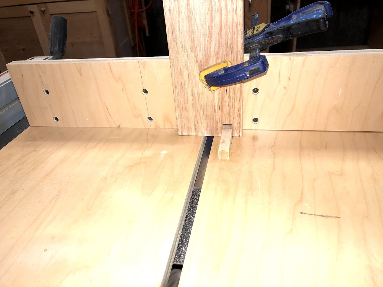
Here is a shot at my workpiece about to crosscut using my Miter Gauge and sacrificial fence.

My miter gauge is made by Incra and it has more precise angles which was way better than the stock miter gauge that I got with the table-saw, but if that’s all you have it work just fine.

Here are all the pieces needed to make the Serving Tray and they are all cut to their final dimensions, this image shows their actual orientation in the tray.
SOME LAYOUT WORK
Now that all my work pieces are cut to final size I went about doing some layout, although I took a few pictures of the process my plans are way more detailed, but more about that later.
To start I laid out all the lines for the finger joints on the front/back & side pieces and that is below.
Then I made all the layout marks on the sides which has a lot going on with them, including a hand hold, finger joints and of course the arc I want to cut in the top of the panel. Which I am seriously thinking of making a template as I want all the arcs on the sides to be identical.

Here is an image of the side & front part of the tray’s frame, I have indicated with an X what needs to be removed on the sides which will make the finger joints.
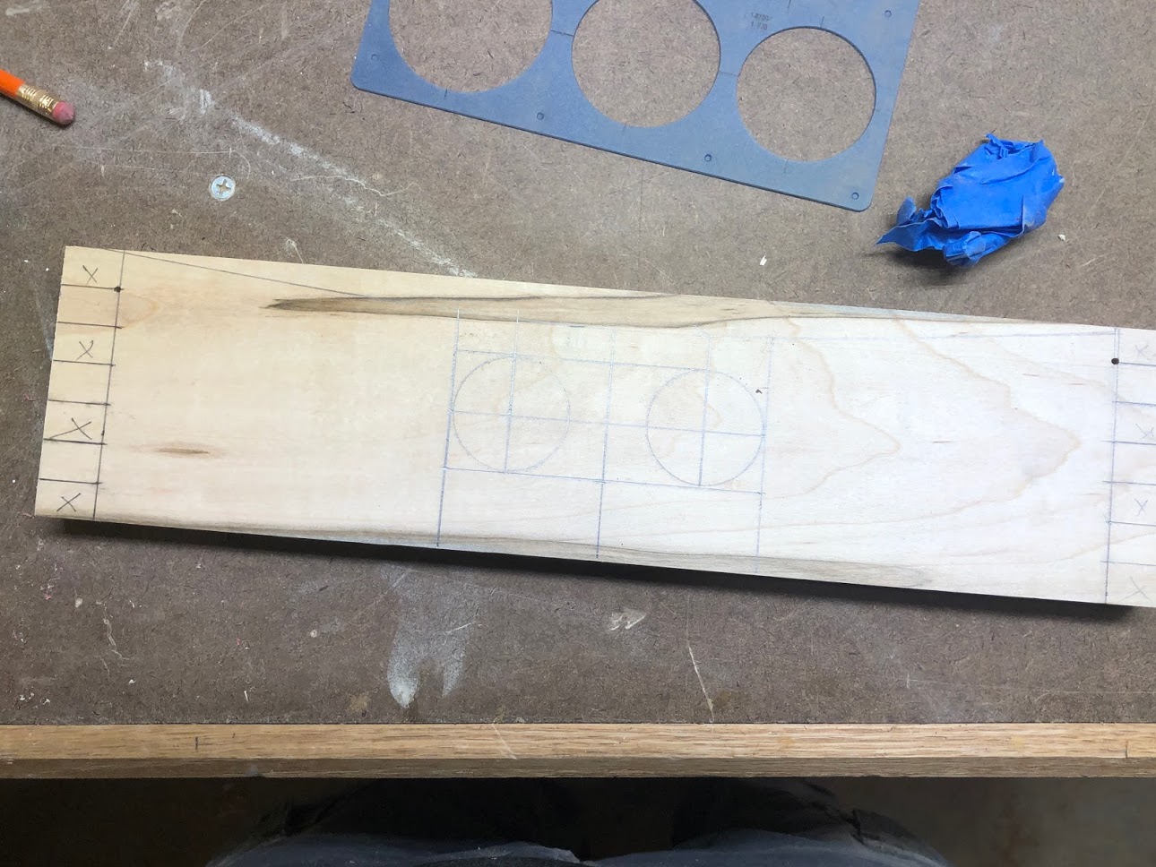
Here is the image of one of the sides with all the layout marks done for the handhold, which is basically 2 holes cut in the center of the board and then the rest of the material will be removed with a jigsaw.
CUTTING THE FINGER JOINT’S
I wanted to use the finger joint to attach all the tray’s sides together because I think it is a very beautiful joint especially when using contrasting woods. Another reason I wanted to use this joint is because I just made the Finger Joint Jig on my last project the C Table.
Below are the steps I took in making the finger joints:
FINGER JOINT JIG
Using my finger joint jig on the table saw I positioned one of the side pieces onto the jig. The way a finger joint works is a series of slots that are cut in a certain sequence so as to reveal a finger. So with this workpieces I decided that I would start with a slot then a finger, but on the mating piece I would start with a finger then a slot so as that they would made together to form what looks like fingers intertwined.
So to achieve the sequence I wanted a lay the workpiece next to a 1/2” spacer which was also beside a 1/2’ key which was glued into the base of the jig, then I will run the workpiece through the blade creating a slot.

STEP 2
With the slot cut out on the workpiece I slid that hole over the key on the right hand side and cut another slot and you just continue all the way down the workpiece until there is no more room for slots to be cut.

STEP 3
So now that I had the sides done and the sequence of a slot then a finger complete, I needed t create the mating sequence of a finger then a slot in these longer boards which will be the serving tray’s front and back pieces.
As you can see I slid the workpiece next to the 1/2’ key in the jig and simply run the workpiece through the blade and that will in turn give the sequence of a finger then a space.

STEP 4
Here you can see the slot being positioned over the key and getting ready to cut another slot, you will need to continue this process on both ends of the boards to complete it.
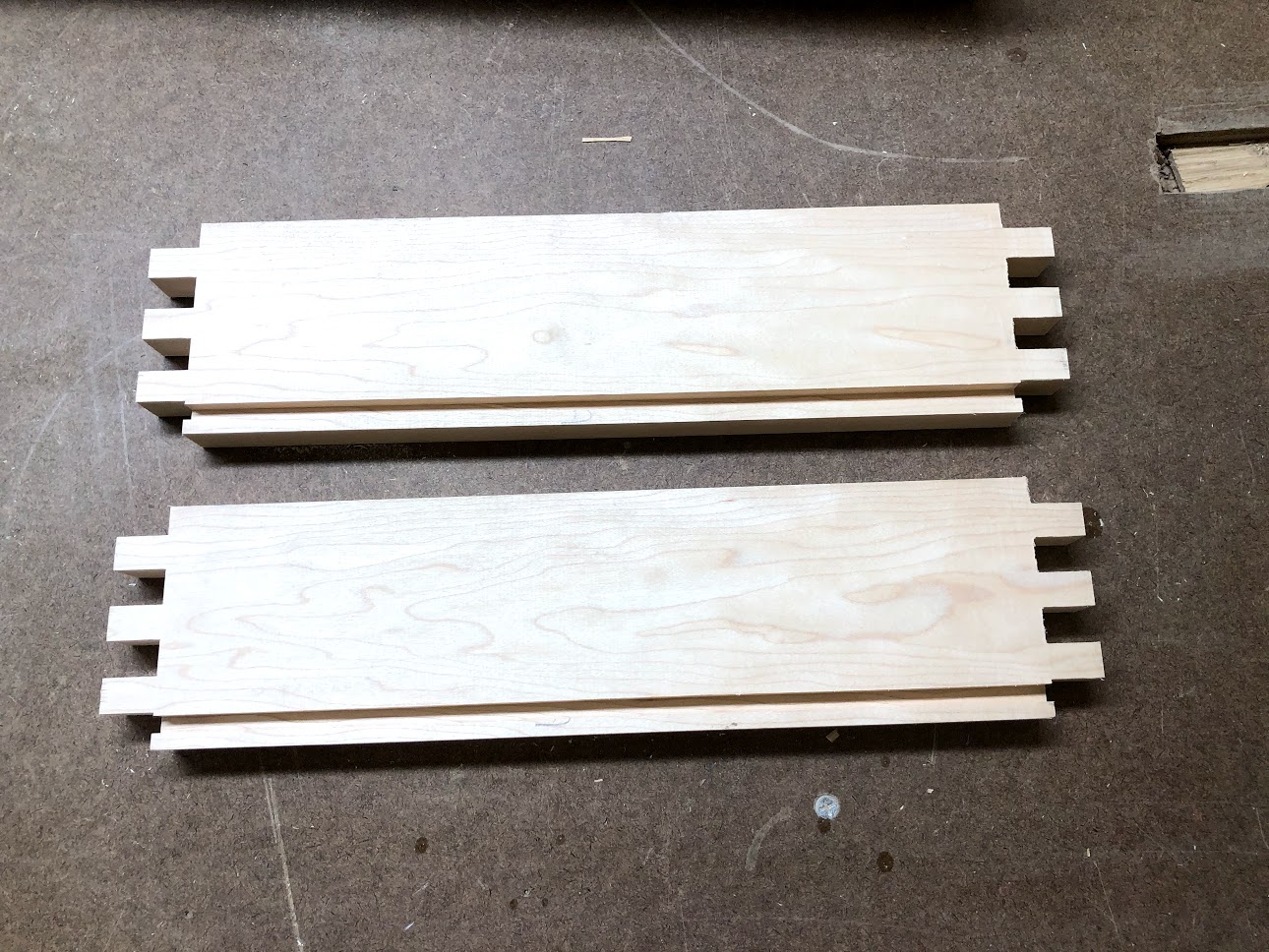
FINGER JOINTS ALL CUT
Here are all 4 boards completed with the finger joints all cut into them as you can see the maple boards have a slot then a finger and the oak boards have a finger then a slot, which when they are mated together will form a very good looking joint.

DRY FITTING THE FINGER JOINTS
Here you can the boards all dry fitted together I wanted to make sure that the joint was easy to put together so as hat when they time came to add glue I didn’t have any problems.

CUTTING SOME GROOVES
In order to attach the base to the serving trays frame I need to cut 2 types of grooves into the inside faces of the frame sides. These 2 types of grooves are
A through groove
A stopped groove
The difference between a through groove and a stopped groove is that one is cut from the left side all the way through to the other side of the board. But a stopped groove is cut within the edges of a board. The reason I am doing this is so as that the grooves will not be seen from outside of the serving tray, they way that I position the stopped groove will be hidden by a finger on the mating board.
CUTTING A THROUGH GROOVE
Here you can see the workpiece inside face down on the router table, I have placed a 1/4” diameter router bit in the router beneath the table. To basically cut this style of groove I just push the entire length of the workpiece entering on one edge and exiting on the other edge and that is it.

THROUGH GROOVE COMPLETED
Here you can see what the through groove should look like.
CUTTING THE STOPPED GROOVE
ENTER & EXIT POINTS
As you can see in the image I still have the same router bit installed in the router beneath the router table, but I have added a piece of tape where the router bit is, this tape signifies the diameter of the bit, the left hand pencil signifies the enter point and the right hand pencil marks the exit point of the bit, once I line up the workpiece with its lines to the lines on the router table I know where to lower the workpiece and also when to lift the workpiece up.
In the end I will have a groove that does not break any of the edges of the workpiece.


Here you can see the stopped groove, see how it does not break any of the workpiece edges.

Here you can the sides all assembled and all the grooves line up, these grooves will fit the base panel later on in the glue up process.
THE BASE
To make the base I decided to use 2 different species of wood like I did for the sides. So I made a panel using 4 boards and joined these boards together using a tongue and groove joint which is also a very strong joint and very useful for making smaller boards into bigger panels.
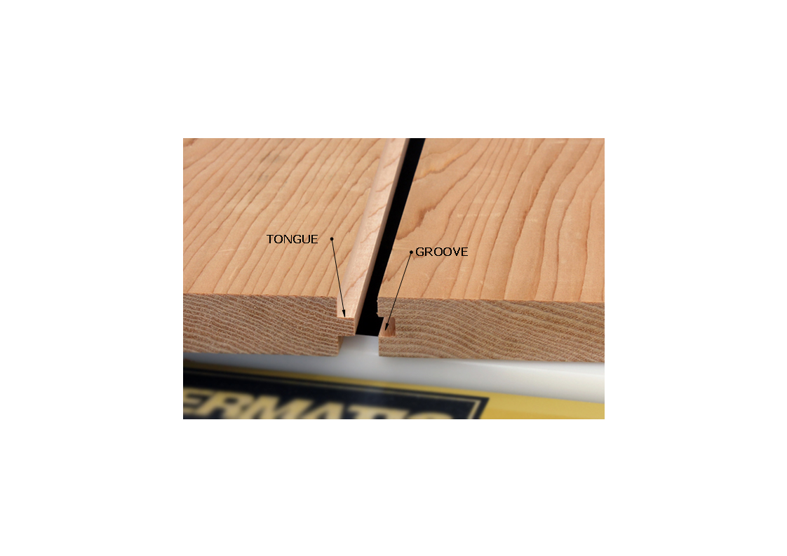
TONGE & GROOVE EXAMPLE
Here you can see an example of what a tongue and groove joint looks like, its a very strong joint because it gives you way more glue surface to glue them together rather than using a simple butt joint that only gives you 2 surfaces to apply glue to.
CUTTING THE GROOVE
Here you can see the workpiece on its edge with a feather-board on the right side to make sure that it does mot move. In the table saw I have 1/4” wide dado stack blade raised a 1/4” high which is what created the groove a long the full length of the board, the groove is centered on the workpiece.

CUTTING THE TONGUE
I lost the images I took of me completing this step so I found this image online, the tongue is created by basically doing to small rabbet cuts on the side edges of the board, I needed to center a 1/4” wide x 1/4” deep tongue centered on the thickness of the board so I left my 1/4” dado stack in the saw & raised at 1/4” and butted my workpiece against a sacrificial fence and pushed both faces over the blade one face at a time after this is completed you will have a tongue centered along the length of the board. Also I needed to add the tongues to the ends of each board as they will be used to adjoin the base into the grooves created in the trays sides.

TONGUE & GROOVES COMPLETED
Here is a completed picture of the tongue and grooves, as you can see they are not all the same the far left board has two tongues this is because I not only needed this workpiece to mate to another board in the base I also needed it to fit into the groove that was created in the trays sides.

V GROOVE
I wanted to define the 4 boards that made up the bottom of the serving tray so to do that I added a chamfer to each edge that abutted another edge in the base. I used my hand plane tilted at 45° and removed a sliver of material, as you can see when the boards are mated together it forms a V.

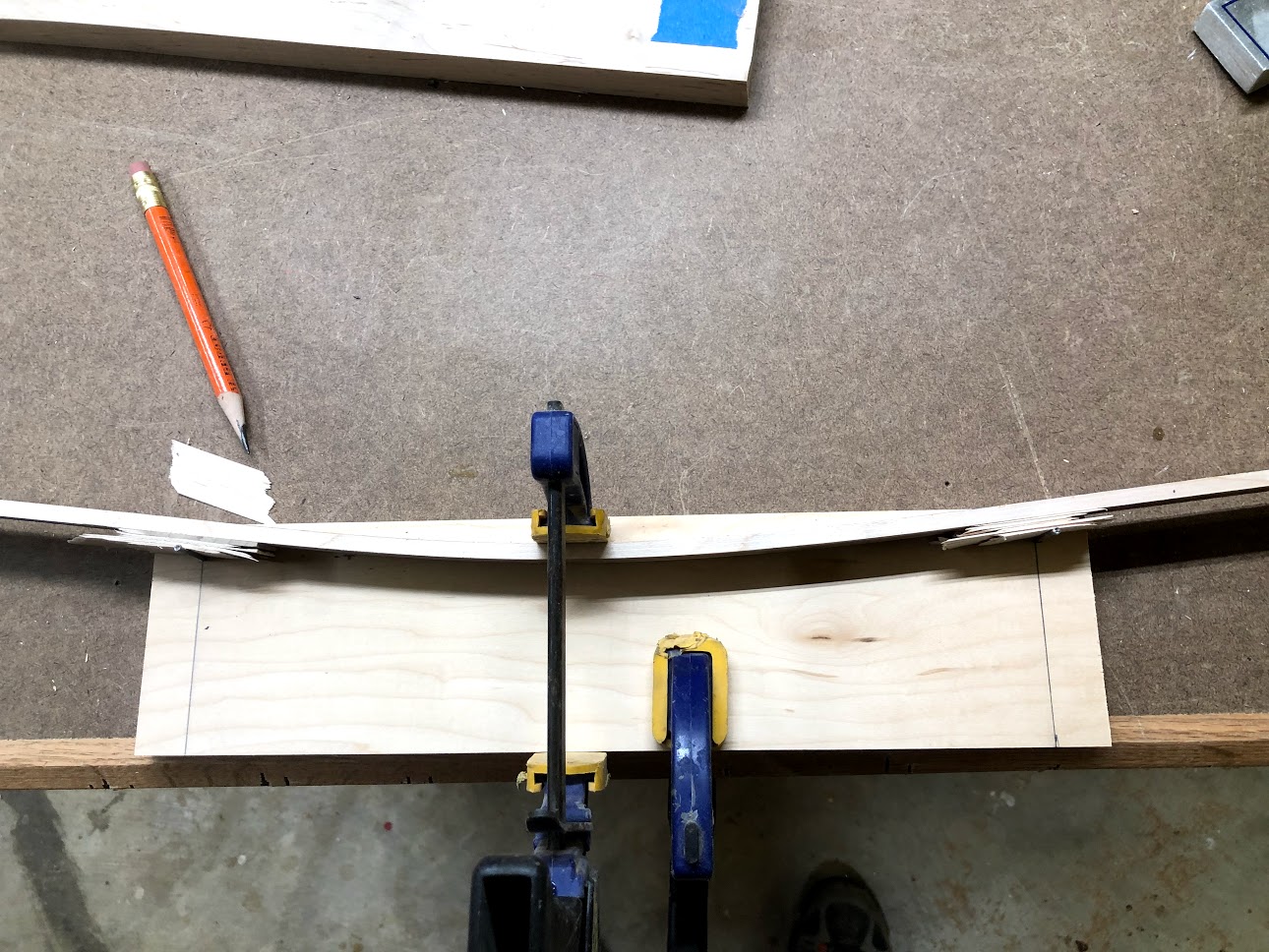
BASE GLUE UP
All that was left was to glue up the 4 boards into 1 big bottom that was to be the base of my serving tray, The glue up had 2important thing that’s I needed to achieve and they were
To join the boards permanently together
To make sure that the panel was flat after the glue had hardened to do this I utilized clamping cauls as you can see the picture’s, I place one caul on top and 1 on the bottom of the base parts and clamped them together that way the boards would not bend out of shape when the glue was setting, after all the bottom had to be flat so as to fit into the grooves I will be cutting into the inside faces of the side of the tray.


mAKING THE TEMPLATE’S
I needed to switch my attentions to making 2 templates that were to be used in the shaping of the tray’s sides, mainly because there was a lot of shaping to do to them. I also wanted the arc’s that I was going to put into the tray’s sides to be uniform and the best way to achieve that was to flush router the actual workpieces with the aid of the templates.
I used 1/2” thick plywood to make both templates. I needed to make two sizes of templates because I will be using them on 2 pieces of wood which are dimensionally different.
Here are the steps I took in making them.
Use the arc jig to draw the layout line
Cut the arc at the bandsaw, making sure to stay away of the layout line.
After cutting the arc out I bring it over to my oscillating spindle sander to sand to the line.
THE ARC JIG
The arc jig is basically a thin piece of wood that I cut about 1/8” thick that way I could bend it easily, I also used shims to push the jig up or down depending on the radius that I was looking for. I held it in place on the template by nailing 2 nails into a board to hold the radius that I was looking for then clamped the jig to the workpiece so as that I could strike my line.

BAND SAW
Next I needed to bring the template over to the band saw to remove most of the waste, keeping in mind to stay away from line that I just made to create the arc, then I simply removed most of the material at the band saw.
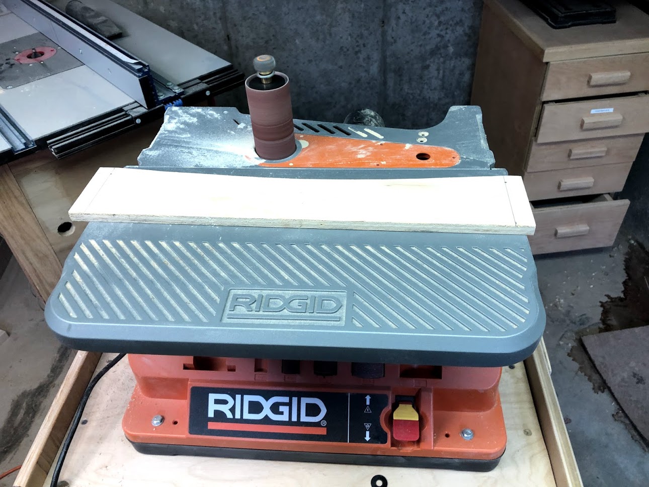
OSCILLATING SPINDLE SANDER
With the arc cut out of the templates I needed to refine the shape and also remove the bandsaw mark making a smooth profile on the arc, remember that I will be using this template with a flush trim router bit so whatever mistakes or bumps are on the template will also be transferred to the workpiece so I took my time making sure that I created a nice and smooth arc.
THE SIDES
The sides have a lot of milling and shaping to them and they also have 1 feature that the other frame pieces do not have and that is hand-holds. I positioned these so as that it could be carried and there was no need to position them on the front and back pieces of the tray. The one feature that all the Serving Tray frame pieces share is that they all have the same arc created into them and that will be next.
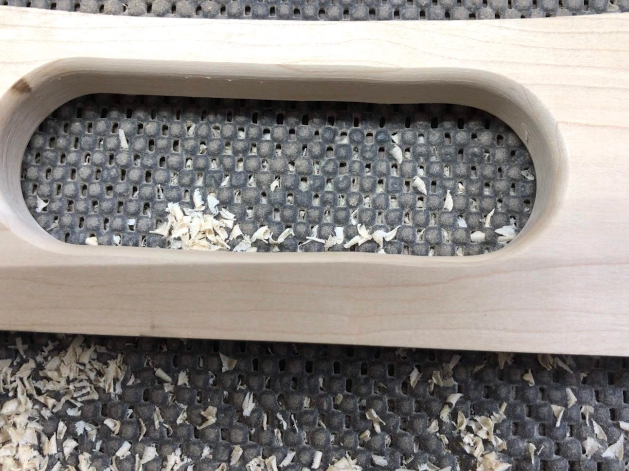
CREATING THE HAND-HOLD’S
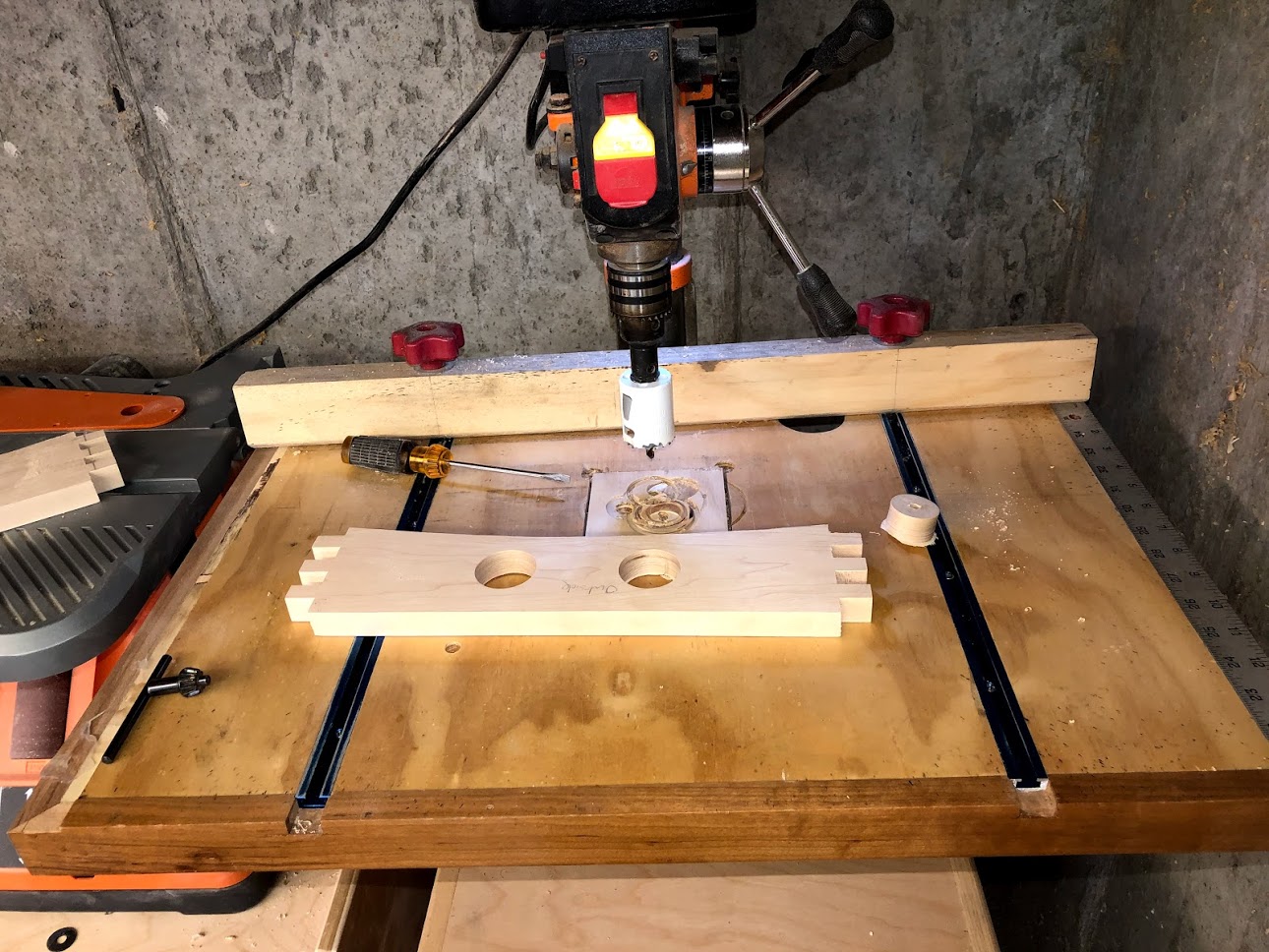
DRILL PRESS :CUTTING HOLES
The hand hold is started over at the drill press with a 1-1/2” diameter hole saw in its chuck, the hole saw creates that arc at each side of the hand hold, all the layout I did beforehand laid out the radius marks to position my hole saw over.
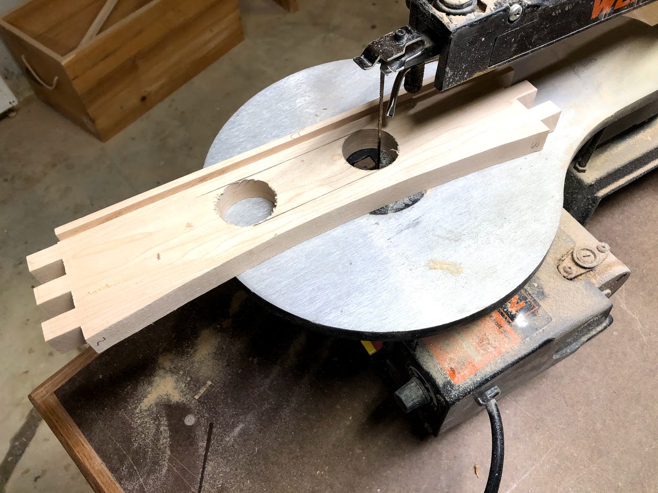
SCROLL SAW : REMOVING THE WASTE
To remove the rest of the wood for the hand hold I used by scroll saw basically because it was easier to do it as I could put the enclosed holes inside the cutting area of the saw rather than use a jig saw to do it, but if that’s the only tool that you have then use it it will get the job done. Again I followed my lay out lines that I had finished earlier and you can see them on the workpiece.

OSCILLATING SPINDLE SANDER
I seem to be using this tool a lot in this project and what can I say I really love using this new tool lately it beats sanding inside curves by hand and there is not better tool at doing this and leaving a silky smooth edge than this. I smooth away all the scroll saw tool marks and made feel really nice to the touch.
ROUTER : ROUND-OVER PROFILE
I wanted to further refine the edges of the hand hold by adding a round-over profiles to its edges, I did this using my palm router installed with a round-over router bit installed and it was done.
CREATING THE ARC’S
Creating the arc that I cut into all four sides of the serving tray’s frame requite a couple of different tools and techniques, but below are some pictures of the process that I took, all pictures are in sequence of my work progress. Although I am only showing 1 picture for each stage of creating the arc I did all these steps to all 4 pieces.
Used my template to draw the arc in pencil onto the workpiece.
Brought all 4 workpieces to the band saw to remove most of the waste.
Installed a flush trimming router bit in my router table.
USING THE TEMPLATE
This is why I made the template, to layout the arcs lines, to do this I simply clamped the template onto the workpiece and hold it in place using 2 spring clamps and struck the line, to be honest making the template is kind of the same procedure of making the tray’s sides.

BAND SAW : CUTTING THE ARC
As I did with the making of the template I used the band saw to cut away most of the material for the arc, remembering to keep away from the lines, as I will be using the router table to finish it.

ROUTER TABLE : TEMPLATE ROUTING
I installed a flush trim router bit into my table and with the template stuck to the workpiece I used it to guide the workpiece , the bearing on the top of the router bit comes in contact with the template and then removes whatever material doesn’t conform to the shape of the template and provides a mostly nice clean edge to the workpiece


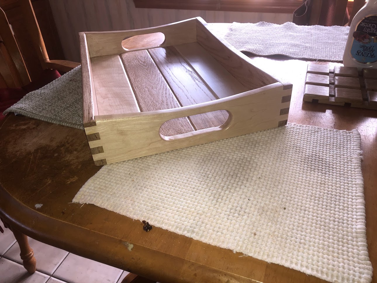
ARC’S ALL COMPLETE
As you can see all the arc’s have been cut out of all the serving tray’s sides and they look awesome. I also dry assembled them to make sure that all the finger joints and arcs lined up with each other and I am glad that they did, this was a decent amount of work for these parts but the pay off is pretty big, it really rings the serving tray into a design all its own.
A LITTLE MORE ROUTING
I wanted to add one more detail to the edges of all the tray’s sides and that is to route a round-over to the edges on the top of the side pieces, this will remove any sharp edges on the tray’s sides and remove any chance of a splinter.
BEFORE ROUTING
Here is one of the tray’s sides before I added the round-over profile to the top edges. its easier to see what has been done in a before and after image otherwise it would go unnoticed.

AFTER ADDING THE PROFILE
Here is the same piece after I added the round-over detail to the top edges I did this to all 4 sides of the tray.

THE GLUE-UP
Well finally we are at the stage of the project where we see the fruits of all our labor the glue up, so far we have worked on each piece of the serving tray on its own. Well the glue up brings all these individual components into 1 piece.
PAINTERS TAPE
I almost always use painters tape in these type of project because it limits the amount of damage that glue squeeze out can cause, once you add the glue to the joint lines you inevitably get glue squeezing out of the joint and it can be hard to remove dried glue from inside corners, with the painters tape there you can just peel the tape and move on and not have to sand the inside corners to remove the dried glue which trust me will take a long time.

CLAMPING TIME
I utilized a lot of my pipe clamps and other clamps that I have, I also used clamping blocks at the corners to make sure there was an even distribution of pressure along the joint lines, you can also see why I used the painters tape as all the squeeze out is on the tape and all I will need it to peel off the tape and I will have nice clean lines and there will be no need to sand or remove dried glue as there will be none.

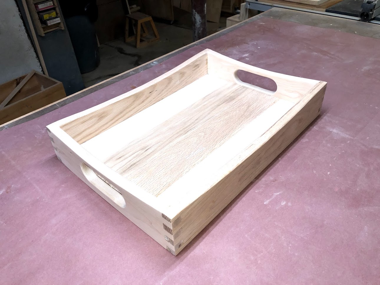
SANDING
Here is the serving tray all glued up and sanded, all that is left is to apply the finish and that is next. I used 100 grit up to 220 grit sand-paper on my Random Orbital sander.
APPLYING THE FINISH
All that is left to do in this project is to apply the finish, I chose a water based polyurethane from Minwax called Polycrylic. I really like this finish as it is a very durable, easy to apply water based finish. It is easy to apply and is extremely durable, any project that I have used this is easily wiped down and consider this project will be used to transport food I need it to be easily maintained.
I applied a total of 3 coats sanding in between each coat to 220 grit sand paper.
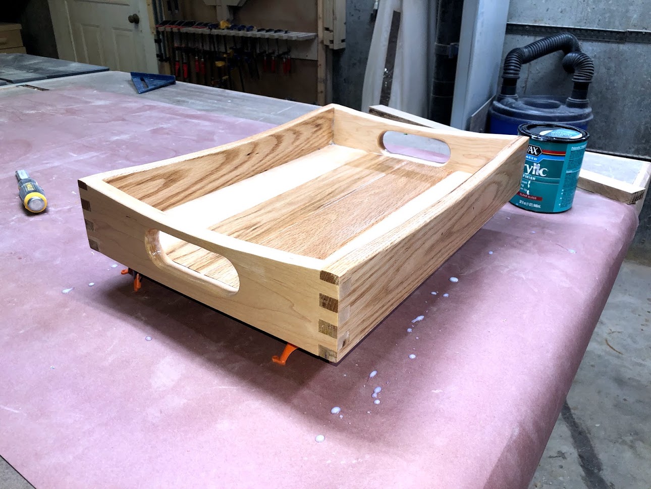
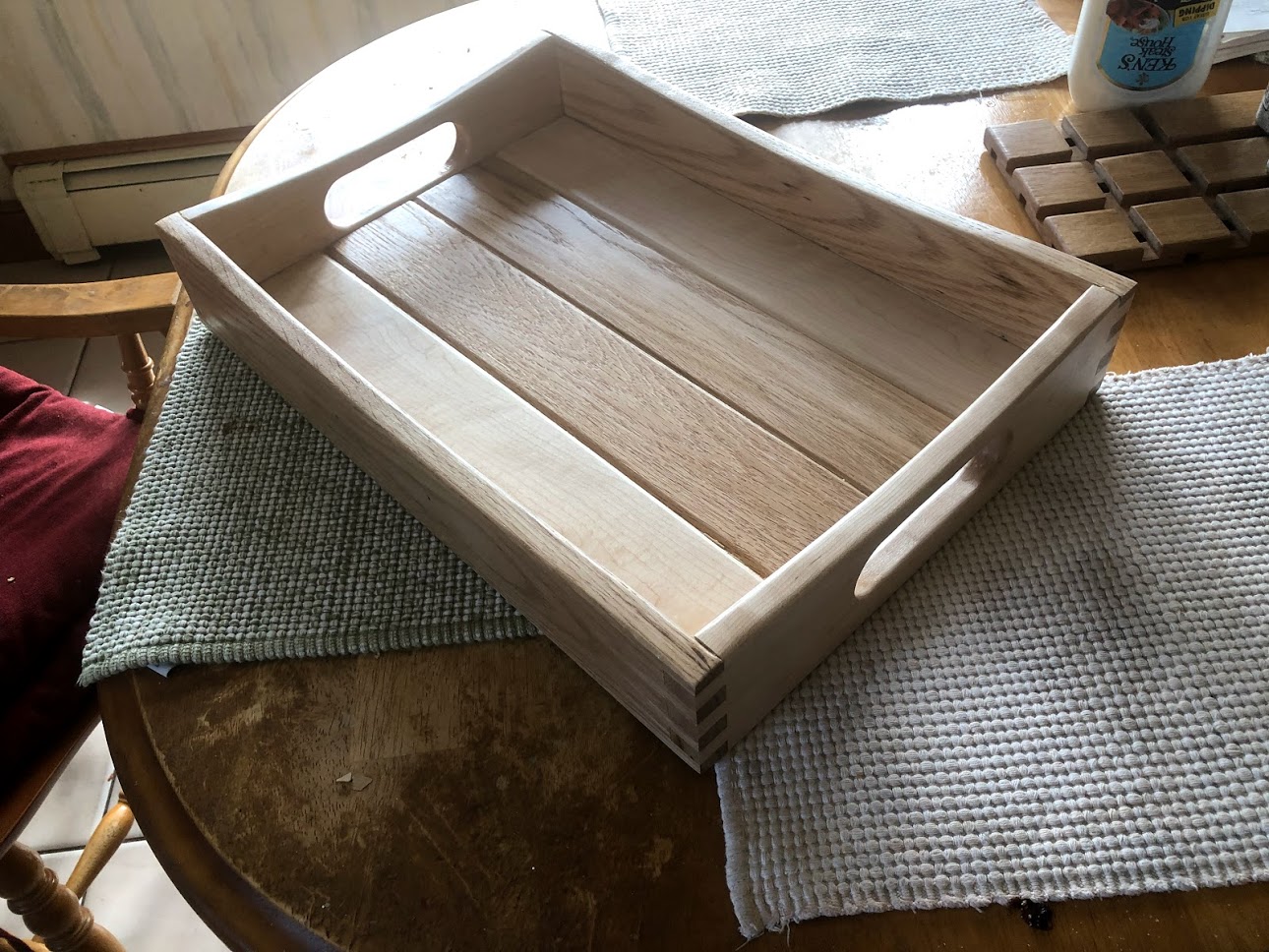
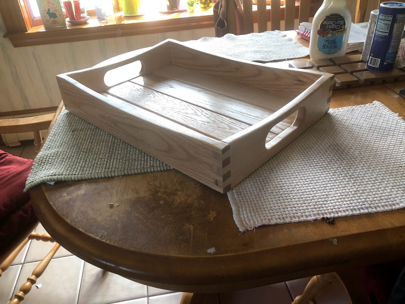
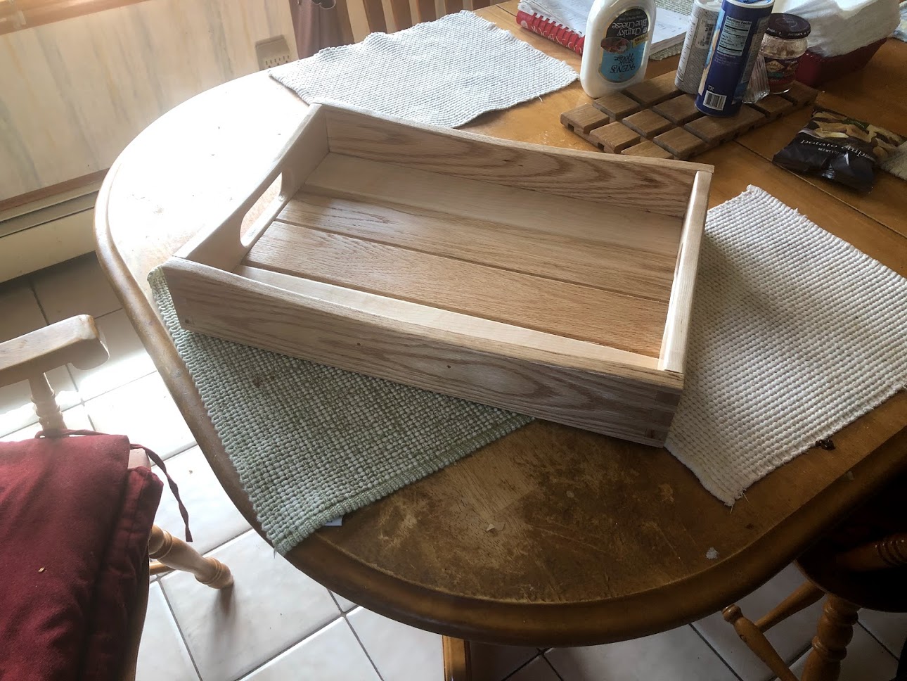
I really love how the finish brings the piece alive.
THE FINISHED SERVING TRAY