Jigs

Project Award : Pipe Clamp Glue Station

A funny thing happened tonight as I was on www.lumberjocks.com website I realized that I was given a Daily top 3 award for this project and I didn’t even know it.

I made this station while I was very busy building and working on my Craft Beer flight blog series and to be honest I threw it together in an hour, took few pictures and moved on.

This is the 7th award I have received in 2018 and I have posted links to all things pertaining to its construction, including free project plans below.

Thanks Lumberjocks.com

badge-daily-top-3.png
 
Click for details: Pipe Clamp Glue Jig
 
Here is a bigger image of the completed station. Its very versatile and it can be completely broken down and stored away when not in use.

Here is a bigger image of the completed station. Its very versatile and it can be completely broken down and stored away when not in use.

Pipe Clamp Glue-up Station

So after yesterday’s glue up fiasco I decided today that I would make a clamping station, something that I have been meaning to do for a while now and I will describe the project below.

  • Research

  • Materials

  • Design

  • The Build

RESEARCH

I found 2 articles online that I used to design this jig, one I found on one of woodworking pages that I am a member of and the other was a YouTube video, links to both are below.

WWW.LUMBERJOCKS.COM

I really liked this concept because of a couple of reasons.

  • It was quick to make

  • I could use scrap plywood, so it didn’t cost anything

  • I could collapse the jig and store until I needed it

  • I could customize it, I could make any length I wanted depending on the usual size of glue-ups I do, I could also make different sized stretchers depending on what size clamps I would be using.

The other resource that I found was a YouTube video created on a channel called the Woodworkweb and you can see it below.

This guy took a different approach to how the pipe clamps would be secured into the jig, instead of using the half-circle approach , he thought that there was still too much movement when the pipe clamp was sitting on the jig so he created a “V” so as that the pipe would be more secure inside the jig.

He demonstrates this in the video below.

MATERIALS I USED

I decided to use scrap plywood that I had on hand and I couldn’t think of a better project because I could clear some of my stock.

I had a quarter sheet of plywood, so the dimensions I used was 4” high x 40” long piece for the front and back of the jig. I also made 2 different sized stretchers or sides of the jig so as that I could use different sized pipe clamps depending what I was actually gluing up, so I made the stretchers 24” & 36” wide.

DESIGN

I turned to my trusty Sketchup to design the 3D Version of the jig. You can see some pictures of the plans that I made below.

Here is the finished design.

Here is the finished design.

Here is the front & back clamp rail, the front & back are mirror images of each other, you can see the V cutouts that I made and the guy is absolutely correct the bar clamps do sit more securely in the jig.

Here is the front & back clamp rail, the front & back are mirror images of each other, you can see the V cutouts that I made and the guy is absolutely correct the bar clamps do sit more securely in the jig.

Here is the side , again each side is the exact same as each other, and the only thing you need to do to them is create the half-lap joint that creates the joint to secure them to each other, it is also what enables the jig to disassembled and store…

Here is the side , again each side is the exact same as each other, and the only thing you need to do to them is create the half-lap joint that creates the joint to secure them to each other, it is also what enables the jig to disassembled and stored away. One thing to note is the sides has the bottom part of the joint cut and the front/back has half-lap cut into the top part.

Here is an exploded view of the jig, you can kind of see how the parts fit into each other.

Here is an exploded view of the jig, you can kind of see how the parts fit into each other.

I included a link to the free plans at the bottom of the post.
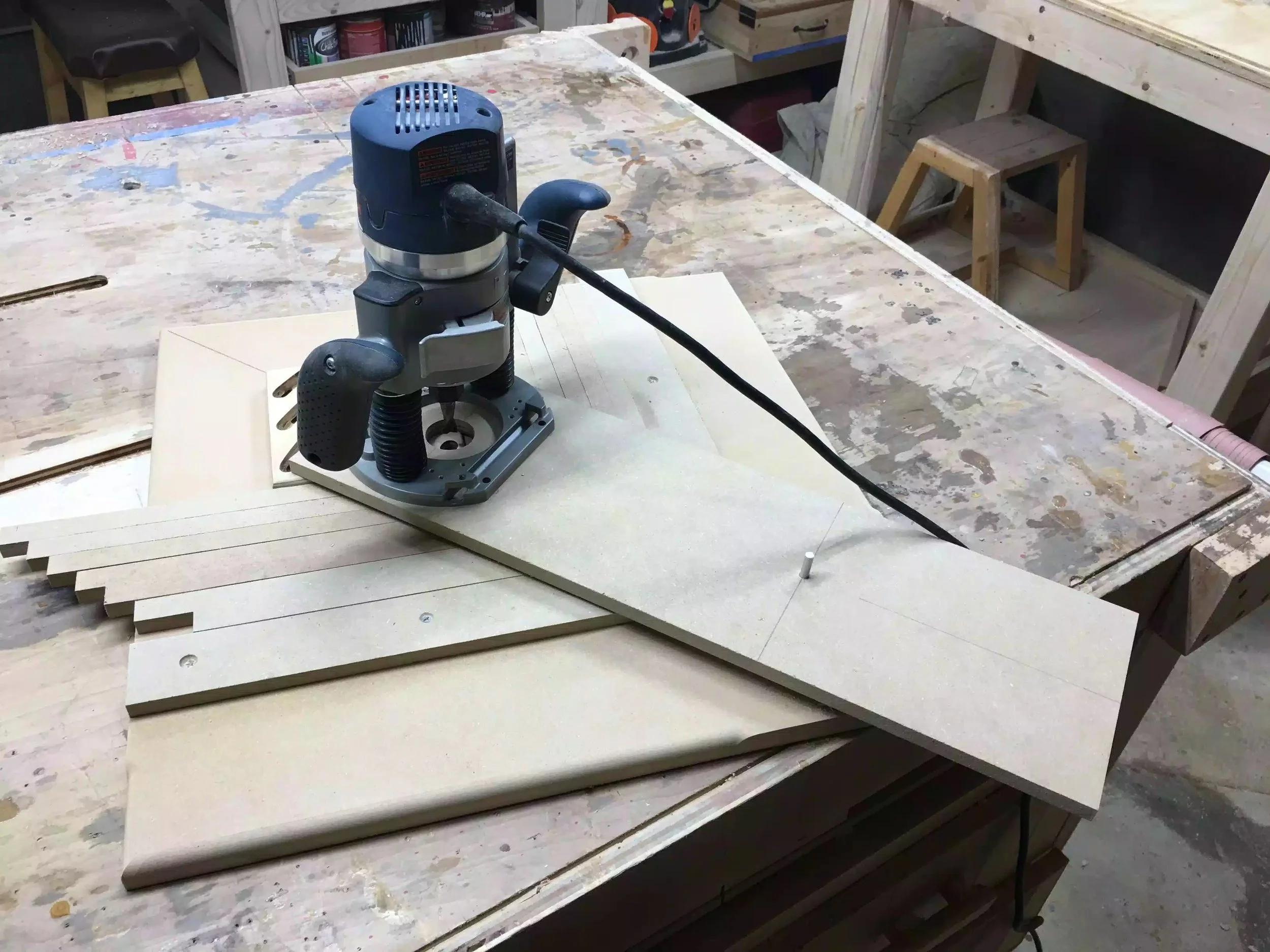
THE BUILD

STEP 1 : I cut the plywood to size which was the following

  • 2 Pieces at 4” wide x 36” (front & back pieces)

  • 2 Pieces at 4” wide x 36” (sides)

  • 2 Pieces at 4” x 26” ( these will be used with 24’ pipe clamps)

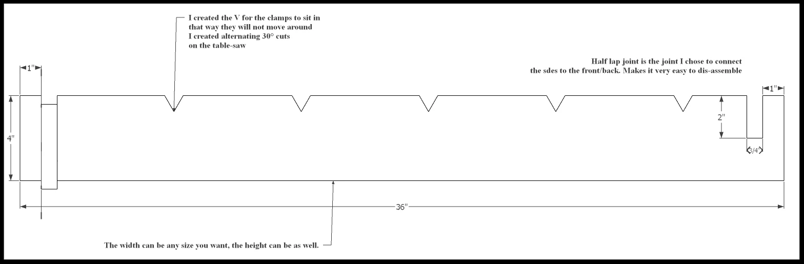
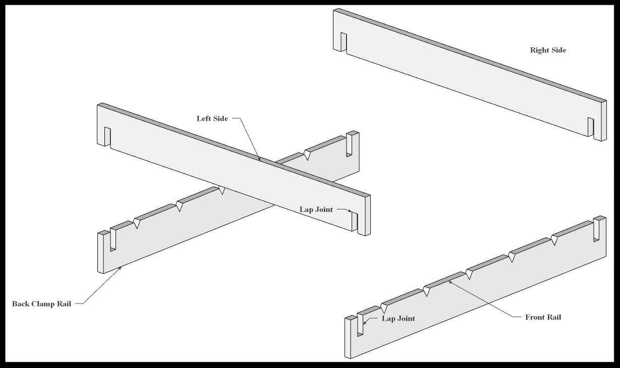
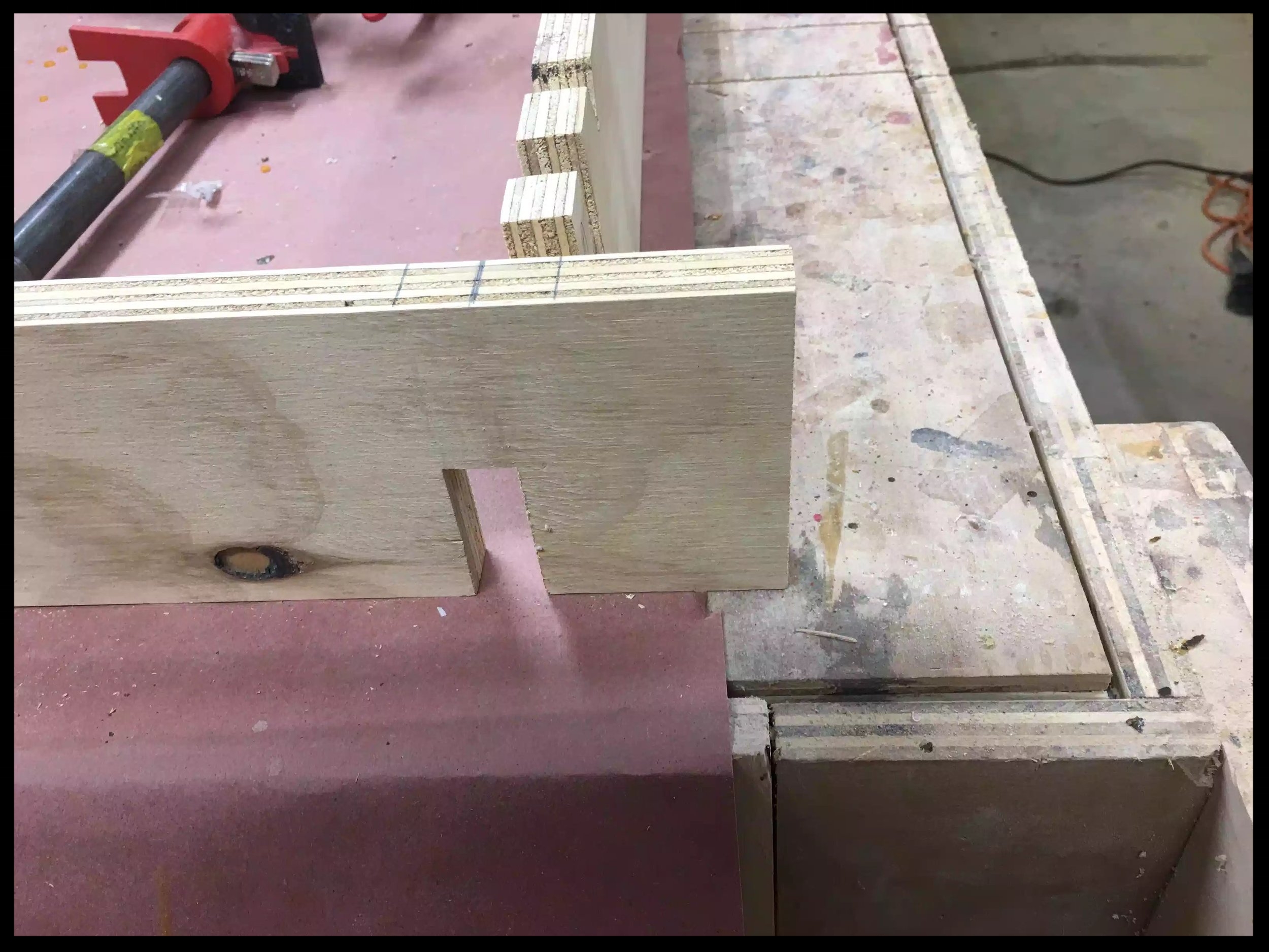
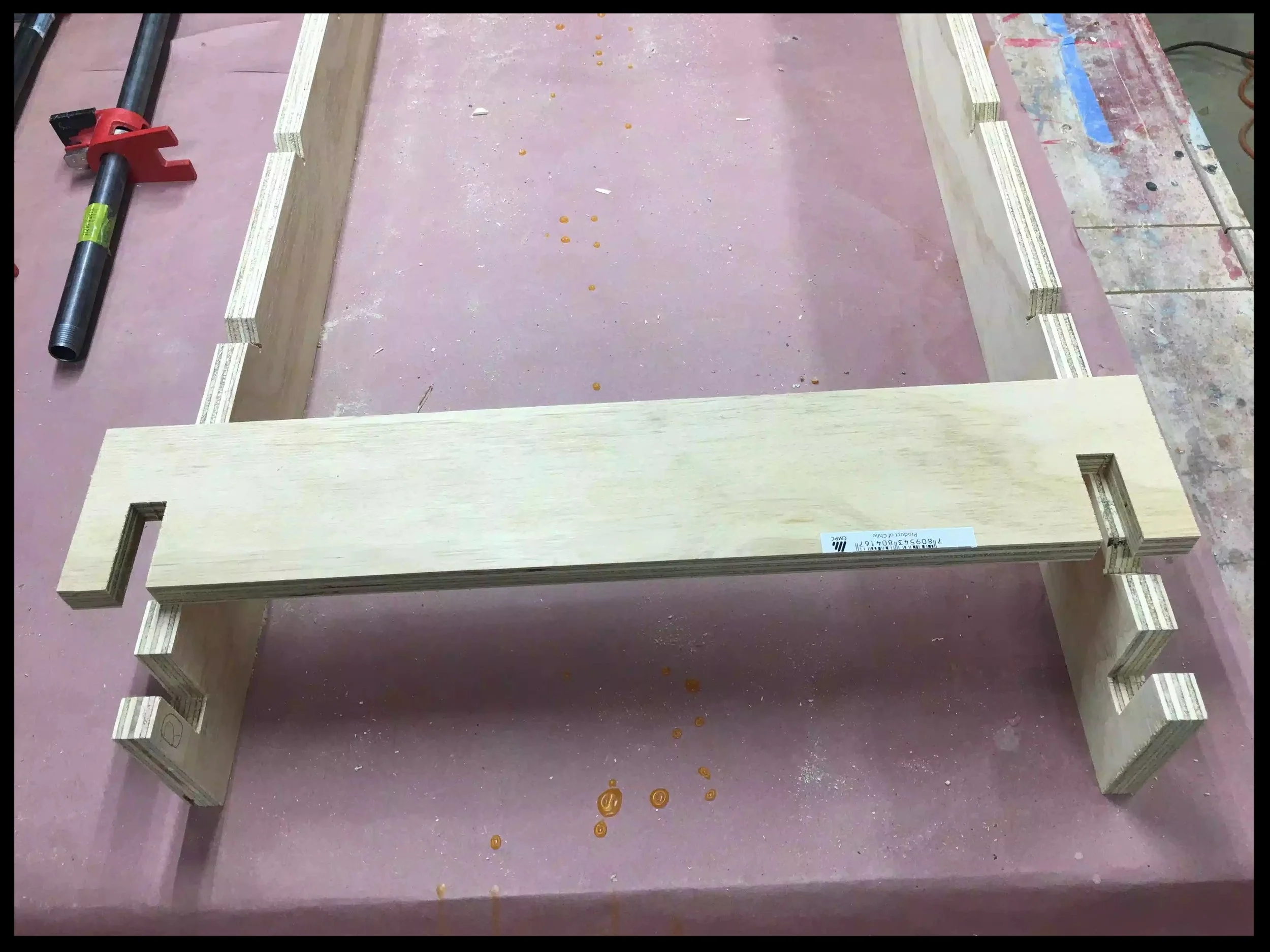
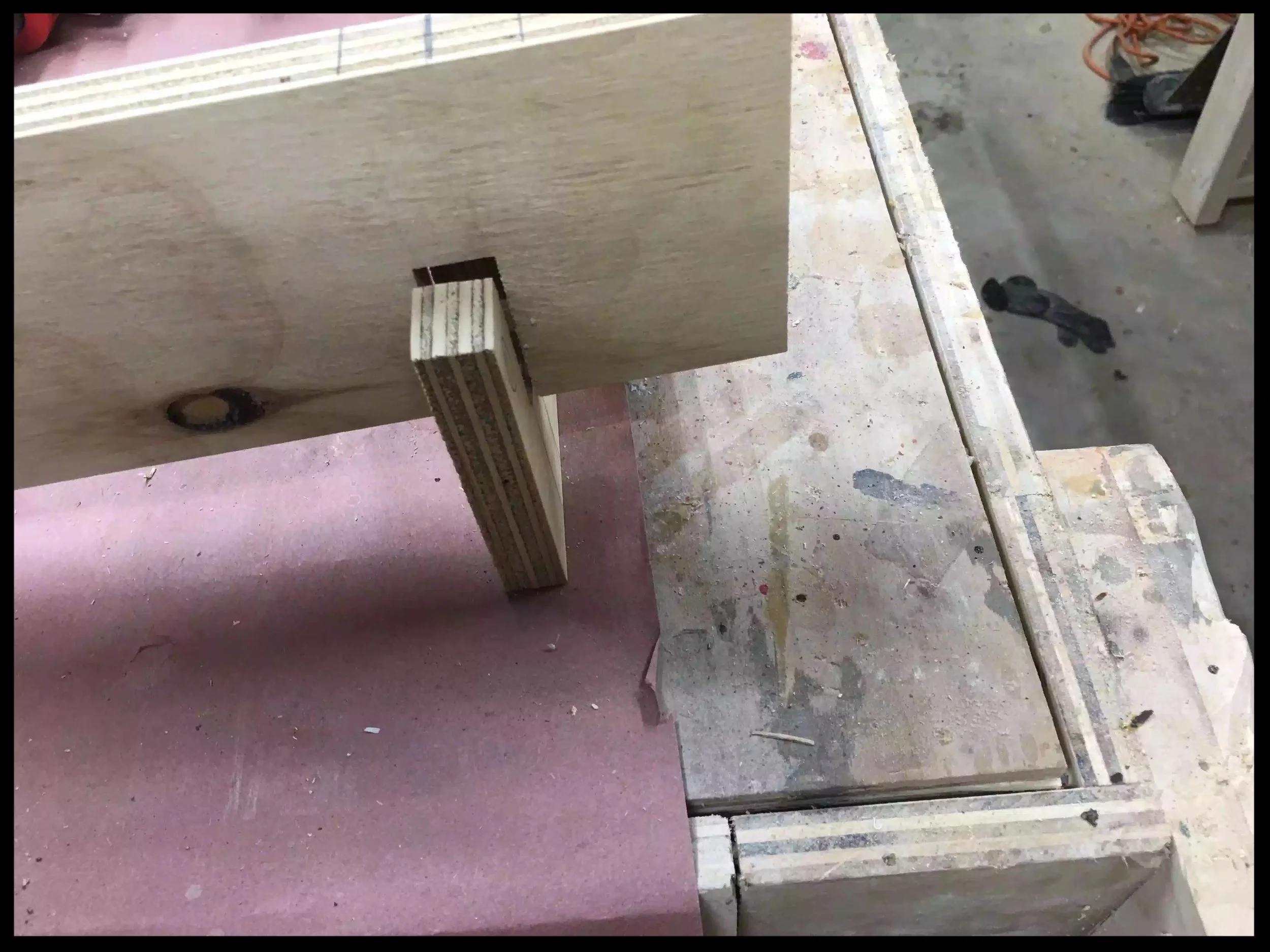
STEP 2 : I marked out where the half-lap joinery needed to be placed so I measured 1” from each side of the front/back parts then using a piece of scrap of plywood marked the position of the lap joint. To avoid making any mistakes mark out the waste for the lap joint ,on the front & back the lap should be removed from the top. The side pieces should have the material removed from the bottom. I could of used my dado stack in the table saw to remove the half-lap waste but 4 only 4 cuts I decided to just leave the regular blade in the saw and clean up with a chisel.

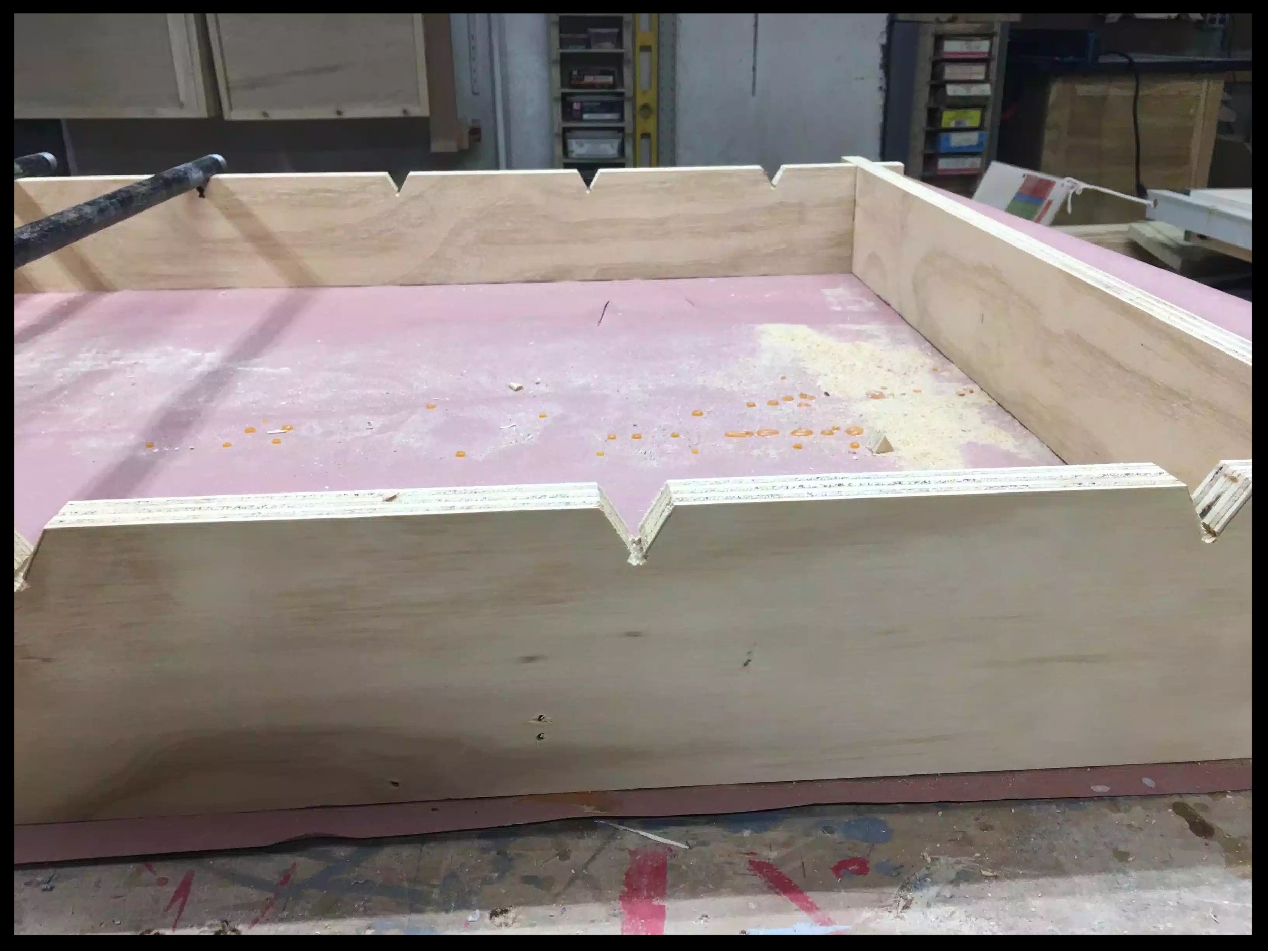
STEP 3 : I needed to add the “V” notches to hold the bar clamps in place.

  • To do this I tilted the saw blade to 30° and lowered the blade to about 3/4” high and made a pencil mark on my miter fence to determine where the starting point of the blade entering the work-piece and then made another adjacent mark about 7/8” away from the other, this marked bot sides of the cut, thus creating the V. I spaced out each V about 5-1/2” away from each other and I got this measurement by laying out 2 bar clamps next to each other to determine what space I needed so as that hat the clamp handles could rotate freely to tighten the clamp without bumping into each other.

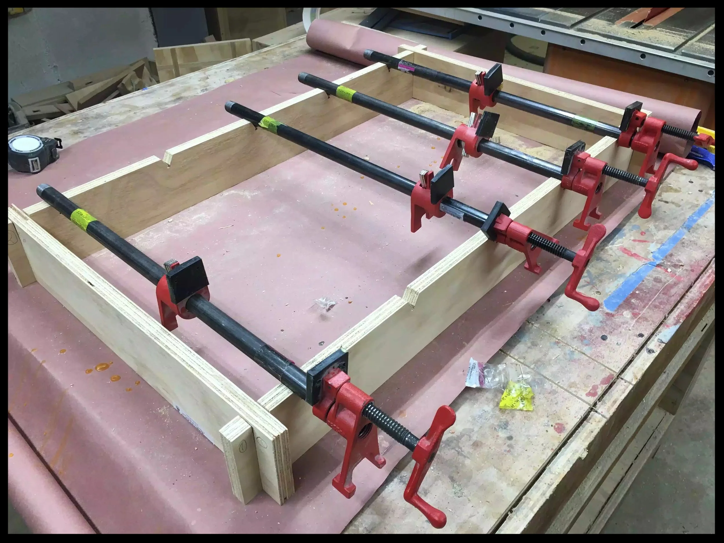
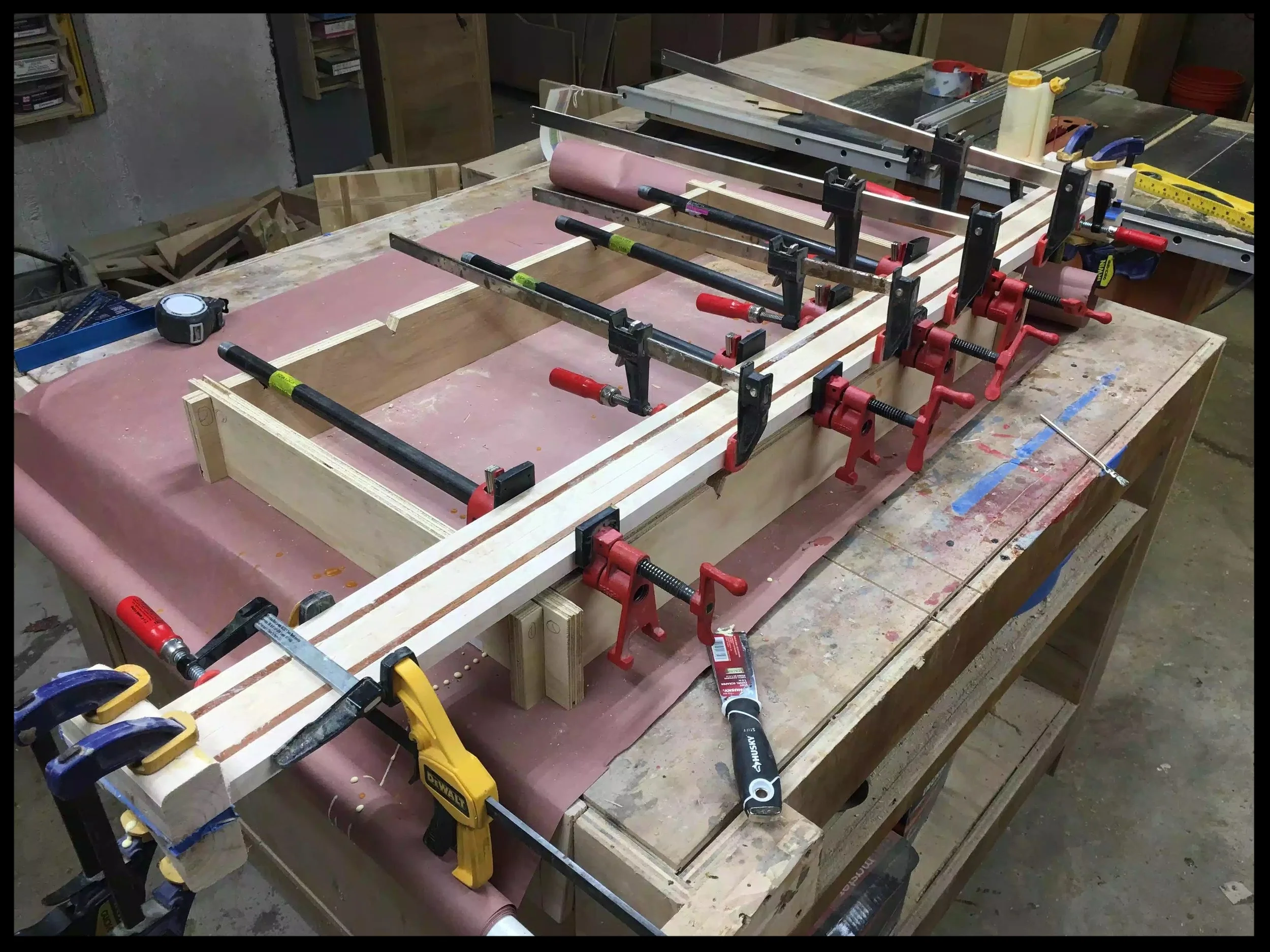
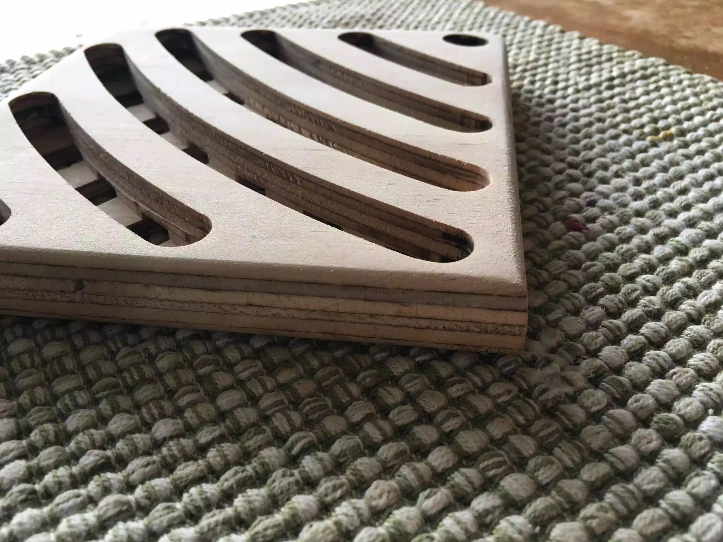
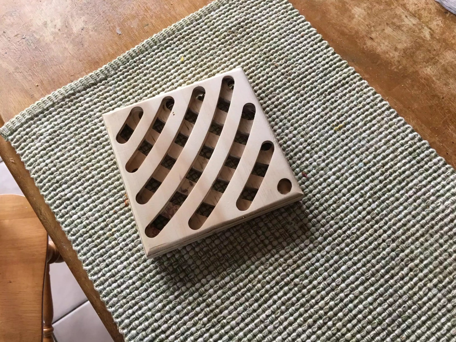
Basically that is all you need to do, I posted pictures below to show some of the features of it and I actually got to use it today for another Project that I am working on “The Craft Beer Flight Project”

Here is the finished jig.

Here is the finished jig.

Here is a close-up of the half-lap on the front part of the jig, you can also see the V notched in

Here is a close-up of the half-lap on the front part of the jig, you can also see the V notched in

Here you can see how the clamp sits in the V notch and it works awesome

Here you can see how the clamp sits in the V notch and it works awesome

Here is one of the sides with the material cleared on the bottom of the joint.

Here is one of the sides with the material cleared on the bottom of the joint.

Here you can the side piece with the completed half-lap material removed.

Here you can the side piece with the completed half-lap material removed.

Here is how the half-lap works its an extremely strong joint.

Here is how the half-lap works its an extremely strong joint.

Finally the jig in action, I should have made this a long time ago.

Finally the jig in action, I should have made this a long time ago.

So now that I have solved my glue-up problem I can move back to my main project. I hope you enjoyed this little project, its not the fanciest project but it sure is a functional one.

Wooden Router Trivet Jig

WHY BUILD A TRIVET JIG??

So as of late I have been playing around with the idea of selling and shipping products on my site, but in the past I was really hesitant because of the costs associated with shipping and trying to determine how much to charge for said projects.

That was until I came across a show on YouTube about making and batching out certain projects for sale with minimal cost and time constraints. So that is how I came up with making Trivets because of a couple of reasons.

  • Small (Low shipping weight)

  • Can be made with a variety of woods

  • Can batch 10 or so in a day (without applying finish)

  • I already had an Etsy shop to sell from

Trivet Jig Design

I would love to take credit for this jig but unfortunately it wasn’t me, I came across this jig online at www.rocker.com , the jig’s concept is really easy to comprehend. It’s basically a trammel on a base, the base has 2 fences that hold the trivet blank and you adjust where the slots are cut with spacer blocks. Ill explain in more detail in a later part in this blog.

Here is the completed jig, its basically a base that has 2 fences that form a 90° corner where the trivet gets positioned, and held in place with the fences.

Here is the completed jig, its basically a base that has 2 fences that form a 90° corner where the trivet gets positioned, and held in place with the fences.

Here is a picture of the jig with the trivet blank positioned between the fences, I also used self adhesive sand paper to help keep the blank positioned while using the router.

Here is a picture of the jig with the trivet blank positioned between the fences, I also used self adhesive sand paper to help keep the blank positioned while using the router.

Here is the jig in use, you can see the router attached to the pivoting arm which is how I achieve the curved grooves in the trivet.

Here is the jig in use, you can see the router attached to the pivoting arm which is how I achieve the curved grooves in the trivet.

Although this is a plywood prototype of one of the designs I will be using, I am very happy with this design.

Although this is a plywood prototype of one of the designs I will be using, I am very happy with this design.

STEP BY STEP BUILD

Source Rockler.com


The trammel jig is fairly easy to assemble and, while it doesn't alter router's cutting radius, it allows you to make repetitive cutting patterns very simply. The jig is really simple to build. Start with a 22"-square scrap of 3/4" plywood or MDF, and draw a diagonal line connecting two corners. Cut a 6"-square trammel support from 1/2" scrap and bisect it with a pencil line. Fasten it to the base with glue and brads so the outermost corners of the support align with the edges of the base and the pencil marks of the two jig parts line up. Now rip a pair of 1/2" by 2" fences, cut them to an overall length of 15-5⁄8" and miter-cut one end of each to 45°.

Completed trammel jig (stock photo)

Completed trammel jig (stock photo)

JIG BUILD

Once you've put the mitered ends of the jig fence together against the support block, nail them down to secure them to the base. Butt the fences against the support piece so the tips of the miters touch. Make sure they form a square “pocket” for the trivet blanks to register against before nailing the fences to the jig base. Line the “field” area inside the fences with sandpaper attached with spray adhesive. Later, this will hold the trivets stationary as you rout them. I left the base’s outer corner bare where the trivets and spacers don’t reach it.

After mitering the corners of the fences to 45°, pin them in position and making sure everything lines up using a square. (stock photo)

After mitering the corners of the fences to 45°, pin them in position and making sure everything lines up using a square. (stock photo)

ADDING THE TRAMMEL

Draw a layout line 12" from the center-line of your bit to establish the pivot point of the trammel. The trammel is a scrap of 1/2" material cut 6" wide and 20" long; this width fit my router base nicely. If your router has a wider base, change the trammel width to suit it. Set the router near the trammel’s end to mark mounting holes for screws, as well as to establish where to bore a clearance hole for the router bit. Mark the trammel carefully with two layout lines: one identifying the center-point of the router bit and a second drawn 12" back from this line, before making the bit clearance hole and fastening the router to it. 

Attaching the trammel to the router (stock photo)

Attaching the trammel to the router (stock photo)

NEXT

Slide the trammel along the support block until the router bit touches the outer corner of a trivet blank to set the position of the jig. You’ll need one of your 6"-square trivet blanks to mount the trammel properly on the jig. With the router bit installed, set the trivet blank in the corner formed by the fences and balance the trammel on it and the square support block. Slide the trammel along the support until the inside edge of the bit just kisses the outer corner of the trivet

Positioning the router in order to find the pivot point on the jig (stock photo)

Positioning the router in order to find the pivot point on the jig (stock photo)

ATTACHING THE PIVOT PIN

Use the dowel's pivot point line to find where you can bore a dowel hole to complete the trammel. Make sure it lines up evenly over the support before boring a 5/16" dowel hole through the trammel and support — right into the base. Center this hole on your 12" layout line drawn previously. Now insert a 2" length of 5/16" dowel to engage the trammel’s pivot action. You’re nearly ready to start routing trivets, but first, make up 14 spacer strips from 1/2" scrap. Mine were 3/4" x 14".

Drilling the location of the pivot pin (stock photo)

Drilling the location of the pivot pin (stock photo)

MAKE SOME TRIVETS

Making your first cuts on the trivet face using a pair of spacers along the jig fences and cutting a little deeper than halfway through the blank in the first slot. Start the router and make your first cut, milling to final depth in two passes. I used a 1/2” up-spiral router bit — but any sharp straight bit should do fine. Swing the router clockwise or counterclockwise — either works fine, but keep the trammel pressed down firmly against the trivet blank to prevent it from shifting.

Begin routing the design (stock photo)

Begin routing the design (stock photo)

Continue adding and subtracting spacers and feeding your router clockwise and counterclockwise to make further cuts, but keep the trivet stationary as you pivot the router. Once you complete the first cut, pull the trivet forward, insert another pair of spacers and repeat for the second, longer “swoop.” Continue adding spacer pairs between subsequent cuts until you reach the other corner of the blank. Now flip the blank over, give it a quarter turn to establish the “X” pattern and repeat the whole routing process. This time remove one pair of spacers after each pass.

Adding spacer strips to maintain equal gaps between the grooves. (stock photo)

Adding spacer strips to maintain equal gaps between the grooves. (stock photo)

FLIP THE TRIVET

Flip the trivet and give it a quarter turn to make an "X" cutting pattern on the second face, continuing to cut them in the reverse of how you made the first side. In minutes, you’ll have your first trivet knocked out and be on to the second. Sand away any bit burn marks or fuzz, and round over the edges

The waffle pattern is coming to life. (stock photo)

The waffle pattern is coming to life. (stock photo)

THE above step by step guide is taken from the Rockler.com article as well as all the pictures, but below is a trivet that I made and looks OK, it will look even better when I actually get to use some really nice wood and not the plywood prototype that I used below.

Not too big and not too small, this prototype will look great in oak or ash.

Not too big and not too small, this prototype will look great in oak or ash.

Adding a round-over to both sides of the trivet really feel great to the touch and doesnt look too bad either.

Adding a round-over to both sides of the trivet really feel great to the touch and doesnt look too bad either.

Love the dimensional aspects of this little project.

Love the dimensional aspects of this little project.

I still need to do some research on making these and eventually with a bit of luck will be able to sell them in my Etsy store… I will also be making FREE PLANS for the jig once its completed I will posit it in my shop, don’t worry I will post when their available.

Thanks for reading, and I will catch you all again soon.